This page works through the sometimes subtle details of using Rhythm Sequencers in practice. It’s recommended that you read the Rhythm Sequencer Module page first for an overview.
Table of Contents
Basic Operation
To function, the Rhythm Sequencer needs to be driven by a V/Bar signal.
The setup below shows a Song Control and a Song Part module configured to create a basic Song Control Sequencer that feeds a V/Bar signal to the Rhythm Sequencer.
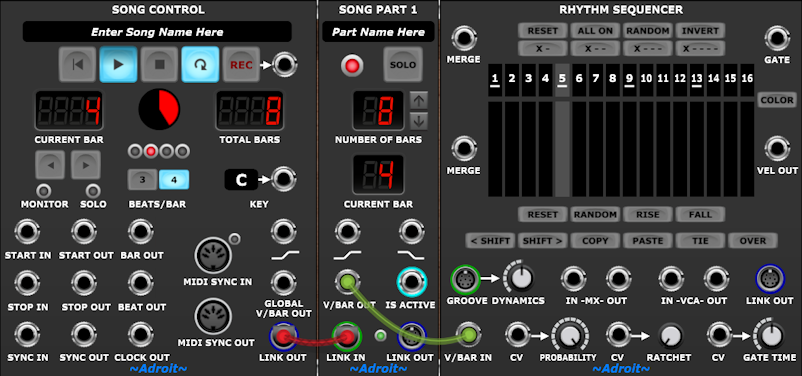
Pressing the Play button on the Song Control module will make the Rhythm Sequencer run for 8 bars and then stop. If the Loop button on the Song Control module is engaged then the Rhythm Sequencer will play continuously.
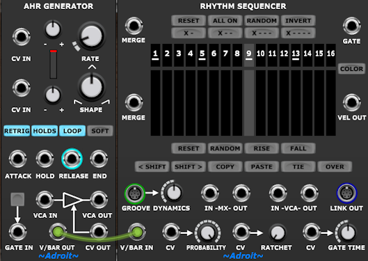
An alternative is to use the V/BAR OUT from an AHR Generator either to create a one-off triggered sequence or a free-running repeating sequence if the generator’s LOOP button is engaged…
Normally the Rhythm Sequencer cycles at a rate of one complete sequence per bar. However, this relationship can be changed by manipulating the V/Bar signal with a Time Flow Changer module.
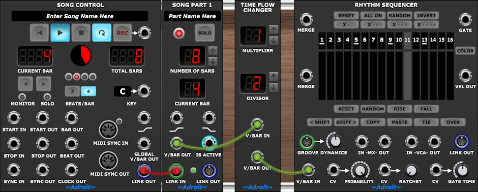
In the image above the Time Flow Changer is set to 1/2 so the Rhythm Sequencer will receive half of the V/Bar voltage and therefore run at half the speed – in this example repeating four times rather than eight times for each loop of the Song Control Sequencer.
But for now let’s return to the original setup with no Time Flow Changer being used.
To illustrate the operation of the Rhythm Sequencer a CV Watcher module can be wired up as follows…
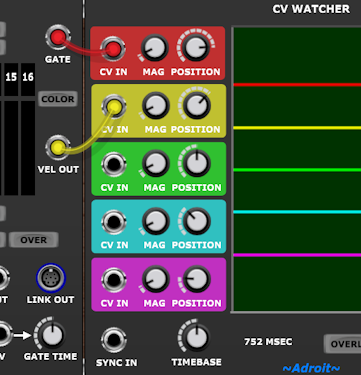
The TIMEBASE control on CV Watcher can be adjusted to zoom in and out on the traces.
Gate Pattern
By default the sequencer’s numbered gate buttons are all off. To switch them all on either click on the ALL ON button or left click on button 1 and swipe the mouse all the way to button 16 while keeping the mouse button pressed.

With the TIE button disengaged, the GATE output will then be a steady stream of pulses as shown by the red trace on the CV Watcher module.
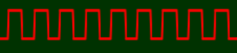
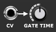
The length of these gate pulses can be adjusted with the GATE TIME knob or by a control voltage fed to the CV IN socket to the left of the knob.
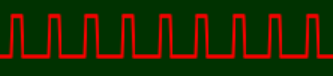
The CV Watcher trace above shows the default 50% gate setting, while the trace below shows the gate pulses when GATE TIME is set to 25%.
A click on the upper RANDOM button will switch the gate buttons to a random pattern such as the following…

This pattern produces the following stream of gate pulses…

Note that each step that is on produces its own individual pulse.
Now engage the TIE button.

Now adjacent gate buttons that are switched on produce a single sustained pulse – the steps are tied together into notes that last longer than a single step.

The Rhythm Sequencer’s gate output might typically be used to control an ADSR envelope generator (or perhaps an AHR Generator) or MIDI note generators such as Chord Player or MIDI Drum Kit, but it’s just a standard 5 V gate signal so can be connected to any module that responds to gates or triggers.
Velocity
The main use for velocity is to allow individual notes to have controllable accents.
The VEL OUT signal is simply a 0 to 5 V voltage so you could use it to control something like the cutoff of a filter. The velocity also controls the gain of a built-in VCA so it’s easy to use it to affect the loudness of a mono voice (or you could use the VCA to control the strength of some modulation).
One interesting application for velocity is to use it to control one of a Rhythm Sequencer’s own parameters. For instance by patching VEL OUT to the PROBABILITY CV input and turning down the PROBABILITY knob you can use the sliders to control the probability of individual steps firing.
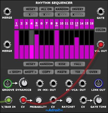
Velocity editing
Velocity information is tied to the start of a note and as the Rhythm Sequencer loads with no gate buttons engaged then there’s initially no velocity information.
When a gate button transitions from off to on the velocity for that step is set to a default value so if we click on the ALL ON button at the top of the module when all gates buttons are disengaed then we will end up with all gate buttons engaged and all the velocity bars set to the default value.
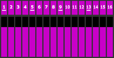
Now assuming that that the TIE button is disengaged we have 16 notes (one per step) and we can begin to play with the velocity bars. Click on the RISE button to generate a rising velocity pattern…
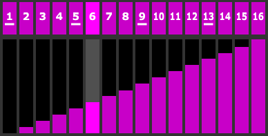
An attached CV Watcher will show what the outputs are doing…
If we “draw” with the mouse on the velocity bars we can define a contour…
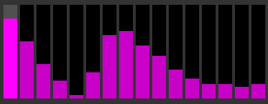
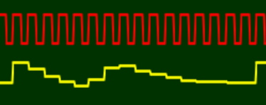
And this will be reflected in the CV Watcher traces…
Interaction between Gate Pattern and Velocity
One important thing to realise is that the velocity information is linked to the gate information. In the world of keyboard instruments velocity is the speed that a key is pressed when a note starts.
So using the velocity contour drawn previously, if we for disengage the gate buttons for steps 8 through 11 then the velocity for those steps becomes the velocity “inherited” from step 7.
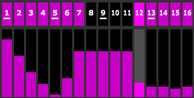
Although the previous velocity information is thrown away you can recover the information by undoing the operation, but only by also recovering the state of the gate pattern.
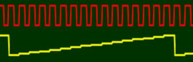
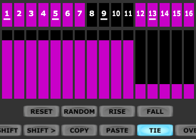
The same kind of thing applies when the TIE button is enaged – with the gate pattern shown above there are only two notes in the sequence, so therefore only two velocities…
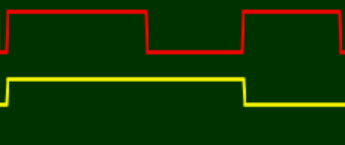
The gate is high for steps 1 through 7, low for steps 8 through 11 and then high again for steps 12 through 16. Note that in fact the gate drops half way through steps 7 and 16 as the GATE WIDTH is set at 50%. Also note that the lower level of the yellow trace isn’t zero volts even though this isn’t completely obvious in the screenshot.
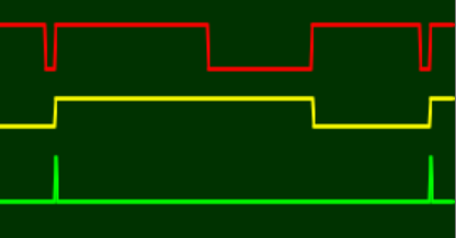
By the way, when studying repeating CW watcher traces it can be useful to patch the BAR OUT socket of the Song Control module to a CV Watcher channel so that you can get a frame of reference. For example the gate and velocity trace above can be identified more easily by using this trick to mark the beginning of the bar using the green trace…
The resulting CV Watcher traces would look like this…
It might take a little while to get the hang of what’s going on with the relationship between gate pattern, ties and velocity, especially if you are used to a sequencer setup that outputs velocity information on every step. But if you think about it, there shouldn’t be any change in velocity except when a note begins. Indeed in a setup where there’s a velocity knob or slider for every step then one ought to use a sample and hold module to remove the extraneous information (or laboriously set the controls manually to achieve the same thing).
You may of course want to define a CV for each step regardless of the gate pattern but that’s a job for a CV Sequencer running in parallel rather than the velocity channel of a Rhythm Sequencer.
Although as CV Sequencers don’t track Groove micro-timing, you would use another Rhythm Sequencer with all gates engaged and TIE disengaged if you wanted to do this while matching any micro-timing.
Velocity End State
We’ll discuss chaining Rhythm Sequencers a little later, as this is related, but before then let’s look at what happens to the VEL OUT signal when a Rhythm Sequencer stops (i.e. when its V/BAR IN voltage drops to zero).
If the V/BAR IN signal is zero volts then any signal connected to the upper MERGE input is passed to the GATE output and any signal connected to the lower MERGE input is passed to VEL OUT.
If nothing is plugged into either MERGE input then both the GATE and VEL OUT signals fall to zero volts when V/BAR IN falls to zero volts.
The GATE signal dropping to zero is almost always desirable as the sequencer stopping means no new notes should play and any existing ones should decay.
But the VEL OUT signal dropping to zero is often problematic. Generally we want the velocity to hold at the last value (although if the sequencer’s outputs are being converted to MIDI this is not an issue as the velocity is encoded at the beginning of the note).
In a situation where the velocity is controlling either the built-in or an external VCA the drop to zero will most likely cause an abrupt end to the final note.

But there is an easy way to fix this problem when using a single Rhythm Sequencer – one can simply patch the VEL OUT socket back to the lower MERGE socket of the sequencer.
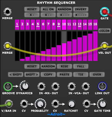
As the MERGE input is now the same voltage as VEL OUT was during the last sample the velocity voltage for the last step of the sequence is sustained as required…
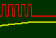
This neat little trick works almost all of the time when multiple Rhythm Sequencers are chained together too – by connecting the VEL OUT of the final sequencer in the chain to the lower MERGE socket of the first sequencer in the chain, but there is a subtle vulnerability to using this method that we’ll discuss later.
Velocity and Leading Rests
One more theoretical thing then we’ll take a breather and load an actual patch so you can experiment with what we’ve covered so far.
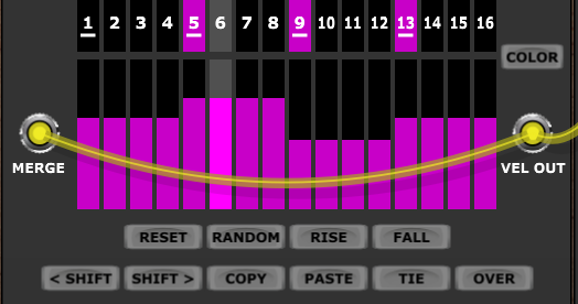
As velocity is determined at the onset of a note, then logically it is unknown before any note has happened (in other words when there are leading rests). So in the following pattern…
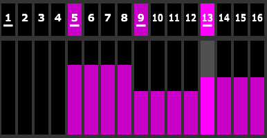
…because there’s no gate for the first four steps then the velocity of these steps is undefined. If you try and change the velocity of steps 1 through 4 you’ll find that you can’t. This isn’t a bug although it might look like one at first sight.
In isolation Rhythm Sequencer will treat this velocity as zero but really it should be whatever the velocity was previously.
When Rhythm Sequencers are chained they can actually discover any missing velocity information from the past via the MERGE mechanism. This also works when there’s only a single Rhythm Sequencer providing that its VEL OUT signal is fed back to its lower MERGE socket as discussed in the last section.
So with the feedback connection from VEL OUT to the MERGE socket then the velocity for steps 1 through 4 becomes the velocity of step 13 once the sequence has run at least once.
This doesn’t happen by magic. The sequence must actually be running for the sequencer to discover what the previous velocity was.
So when you alter the velocity of the note beginning at step 13, by dragging any of the velocity bars for steps 13 through 16 up or down, it takes a while for the velocity bars of steps 1 through 4 to catch up.
At first sight this behavior can look like a bug but it isn’t, it’s a neat feature that allows velocities to automatically sustain across bar boundaries.
Unfortunately the velocity bars will still sometimes display data that doesn’t exactly match the final output when chaining, using the OVER button and Sample & Hold, but most of the time they will show exactly what’s happening.
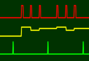
The following CV Watcher screenshot shows the behavior of the gate and velocity over the first two bars…
A Test Patch
We’ve covered more than enough theory for the moment, so now download the test patch below and spend some time experimenting with different gate patterns and velocity settings with and without the TIE button engaged.
Click on the button to download the .voltagepreset file. It’s a tiny file so should only take a second or two to download. When you open the downloaded file it should automatically load Voltage Modular with the patch ready built for you.
More information on downloading presets
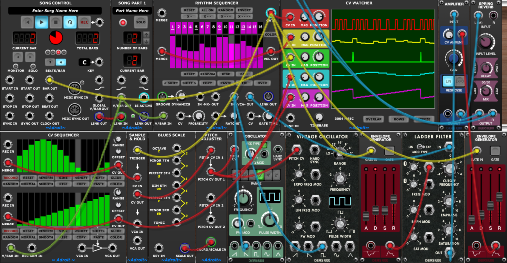
The patch should run with only the free Nucleus version of Voltage Modular and the demo version of LSSP 101 or LSSP XL installed. If you only have LSSP 101 then you can either demo CV Watcher or just remove that module if you prefer.
Tempo isn’t saved as part of a Voltage Modular patch so check that the tempo at the very top of the Voltage Modular window is set to 120 BPM then press the Play button on the Song Control module in the top left.
This will all be second nature if you’ve already gone through the LSSP 101 tutorials.
This test patch is pretty basic and doesn’t do anything fancy with pitch – it’s using a CV Sequencer, quantization and sample and hold to generate fairly crude pitch movement, but it serves the purpose.
The combination of Rhythm Sequencers and Melody Sequencers produces a much more powerful system but it makes sense to learn about Rhythm Sequencers first before looking at Melody Sequencers.
Here are a few suggestions on things to try..
Try engaging the OVER button when the gate buttons for step 16 and 1 are engaged – see how step 16 extends to the end of the bar and instead of two separate notes we end up with one that ties over the bar boundary.
Notice that with TIE, OVER and all the gate buttons engaged we end up with one bar-long fully sustained note.
Check out what happens when the Song Control sequencer stops. See how this is affected with and without the VEL OUT to MERGE feedback cable.
The lower channel of the CV Sequencer isn’t used for anything so try patching its output to the PROBABILITY, RATCHET and GATE TIME CV inputs of the Rhythm Sequencer in turn.
The PROBABILTY knob controls the minimum probability (i.e. when the control voltage is at zero volts). So when the knob is set at maximum the control voltage has no effect. When you unplug the PROBABILTY CV input remember to turn up the PROBABILTY knob because if it’s set fully CCW there’ll be zero probabilty of gates firing!
The RATCHET knob controls the maximum number of repeats (i.e. when the control voltage is 5 volts or above). So when the knob is set at minimum the control voltage has no effect.
The GATE TIME knob combines with the CV input, so acts as an offset to the unipolar or bipolar input.
Hopefully, after playing with the test patch for a while you will have started to develop some “muscle memory” for playing the Rhythm Sequencer.
Chaining Rhythm Sequencers
Rhythm Sequencers can be chained together to form sequences of just about any length.
There are several elements to this – passing control from one sequencer to another, combining their outputs, tying notes over bar boundaries, sustaining velocity across bar boundaries and holding velocity when the whole chain stops.
Let’s begin by chaining two sequencers together so that we have a repeating pattern with 32 steps instead of 16…
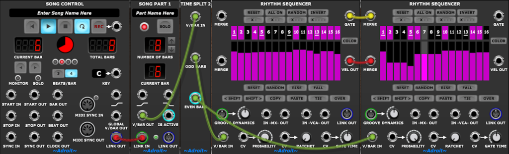
The patch shown above is stripped back to the bare essentials so that you can see how simple the basic wiring is.
The solitary Song Part module is set to 8 bars so the 2 bar long 32-step sequence plays 4 times for each loop of the Song Control Sequencer.
The V/Bar output from the Song Part module is fed to a Time Split 2 module that splits the timing into odd and even bars. During odd bars the Rhythm Sequencer on the left gets a V/Bar signal between 1 V and just under 2 V and the one on the right gets zero volts. During even bars the V/Bar signals are the other way around.
We then need to combine the outputs of the two sequencers. This could be done by adding the signals together but instead we use a merging mechanism that offers tidier wiring and other advantages.
So the gate and velocity outputs of the left-hand sequencer are fed to the MERGE inputs of the right-hand one. The combined output of the two is then available from the outputs of the right-hand sequencer.
This works because inactive Rhythm Sequencers (those with V/Bar inputs of zero volts) simply pass their MERGE inputs to their outputs. No matter how many sequencers are chained together like this, providing that only one is active at a time, the outputs from the active sequencer get propagated down the chain and eventually become available at the GATE OUT and VEL OUT sockets of the final sequencer in the chain.
This mechanism introduces a one sample propagation delay for each sequencer that the signals have to pass through so technically it introduces a tiny amount of bar-to-bar jitter but as one sample lasts less than 21 microseconds this has no meaningful impact on musical timing.
The wiring in the image above is all we need if the sequence runs continuously and we aren’t concerned about velocity sustaining across the bar boundary from the right-hand sequencer to the left-hand sequencer when there are leading rests.
However if the sequence does need to stop and we don’t want the velocity to drop to zero (as discussed in the Velocity End State section above) then we could patch a feedback cable from the right-hand sequencer’s VEL OUT to the lower MERGE input of the left-hand sequencer as shown below.
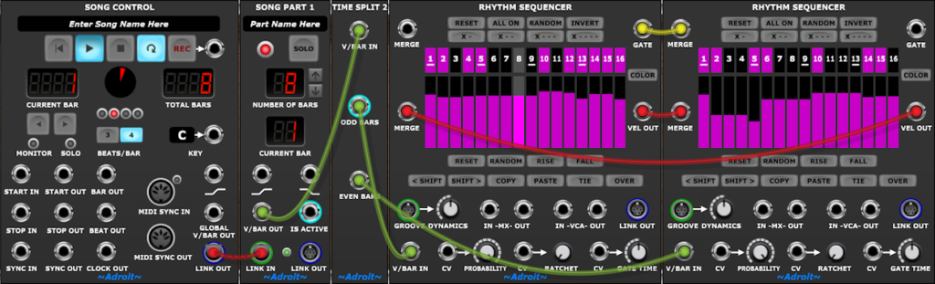
But there is a subtle vulnerability here as there is a risk that the sequence could stop exactly one sample after a step change. Then the two cables in the merge loop could have different velocity voltages and when both sequencers are inactive these two voltages would cycle around and around the loop causing a very high frequency oscillation. In practice the odds of this happening are tiny but it’s best to prevent the possibility. That’s why when chaining multiple V/Bar driven Rhythm Sequencers that need to stop and that use merge feedback it’s best practice to add a Sample & Hold module to the end of the chain.
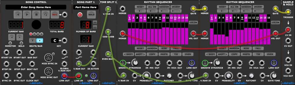
Recommended wiring with Sample & Hold module added
As before the combined gate signal comes from the right-hand sequencer’s GATE output but now the combined velocity signal should be taken from the CV OUT socket of the Sample & Hold module.
The Sample & Hold module samples the voltage fed to its CV IN socket when its TRIGGER input goes high and then holds the voltage until another rising edge is detected.
Once we add sample and hold we no longer actually need the merge feedback cable to solve the velocity end state problem or to sustain velocities when there are leading rests but we might as well leave the feedback cable in place as it helps the Rhythm Sequencers display the sustained velocities.
The VCA built into the right-hand Rhythm Sequencer could be used in the same way as the built-in VCA in the Rhythm Seq Test Patch to make velocity affect the audio signal level but it’s subject to the oscillation vulnerabilty so this would defeat the whole point of adding the sample and hold. So instead we should use the VCA built into the Sample & Hold module as its gain is controlled by the held voltage and not subject to any risk of oscillation.
Download the Rhythm Seq Test AB patch and have a play to see how this works in practice.
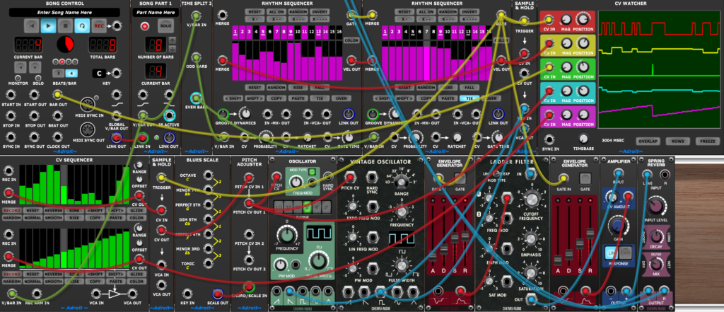
Other Chaining Patterns
In the example above we have two Rhythm Sequencers playing a repeating AB pattern but the same principles apply to other patterns. Note that these chaining patterns don’t need to be linear – so as well as say ABCD we can do things like AAAB or ABAC.
To implement an ABCD pattern i.e. four different sequences in a row, we can use Time Split 4 and four Rhythm Sequencers…
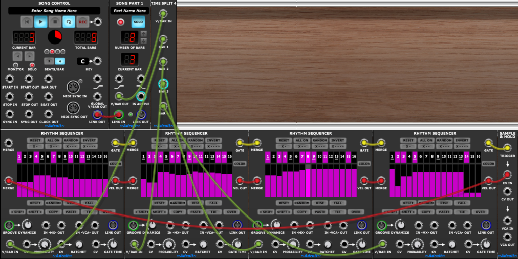
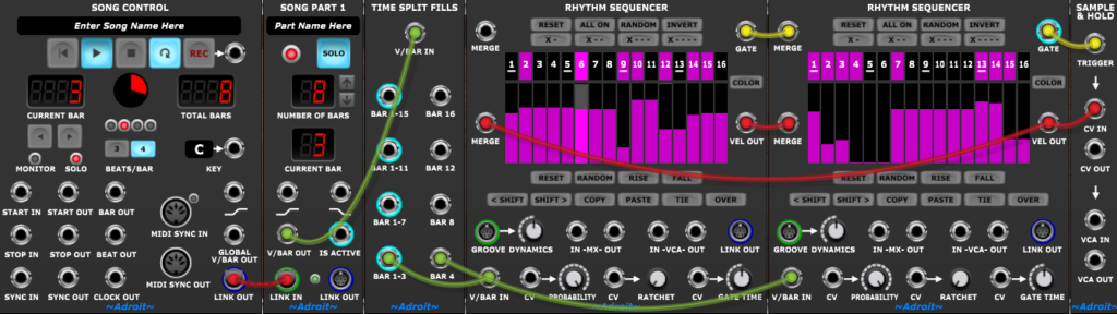
To implement an AAAB pattern we can use Time Split Fills and two Rhythm Sequencers…
To implement an ABAC pattern we can use Time Split 4 again but with three Rhythm Sequencers…
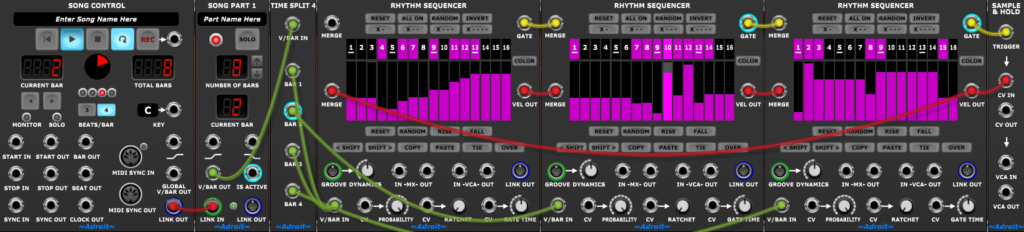
Here both the BAR 1 and BAR 3 outputs of the Time Split 4 module feed the left-hand Rhythm Sequencer.
Notice that the order of the merging connections doesn’t have to follow the order of the sequencing – it couldn’t do with a pattern like ABAC anyway. But it makes sense to follow the basic flow order.
We’ve used Time Split 2, Time Split 4 and Time Split Fills and these are what we might call regular Time Splitters but we could also have implemented these patterns using Song Parts as Song Part modules are in effect just special types of Time Splitters.
So the ABAC pattern could have been implemented like this…
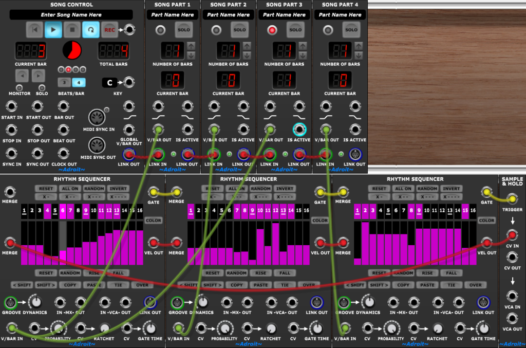
But it’s overkill to use Song Parts like this. Song Parts are better used to define high-level structure such as verse/chorus/break etc rather than low-level patterns.
Time Splitting isn’t limited to a flat system. We’ve already been using two levels of hierarchy even when there’s only been one Song Part module, but let’s look at an arrangement that uses two levels of hierarchy more explicitly with the upper level using two Song Part modules and the lower one using a Time Split 2 module and a Time Split Fill module…
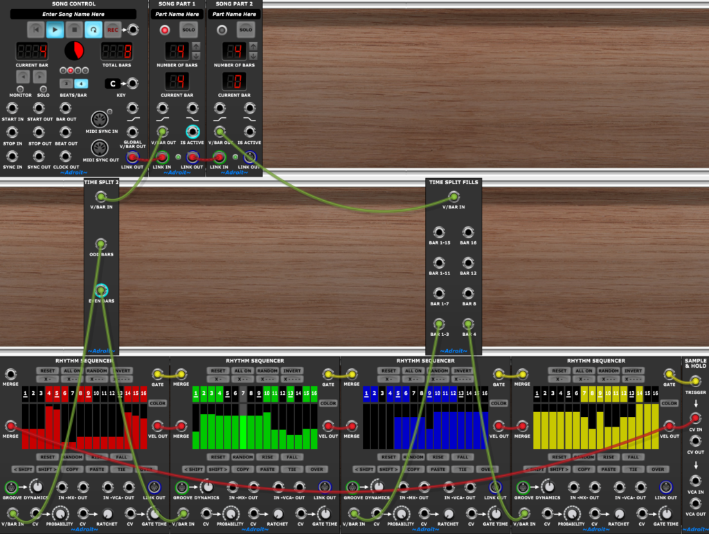
The Rhythm Sequencers have been color coded here (using their COLOR buttons) and this patch plays the sequencers in the following eight bar long pattern:
Red, Green, Red, Green, Blue, Blue, Blue, Yellow.
There isn’t really any limit to the scale or complexity of the hierarchical structures you can build other than your computer being powerful enough to run patches that contain a very large number of modules.
We’ve been talking about Rhythm Sequencers but most of these techniques can be applied to chaining LSSP sequencers in general.