Table of Contents
Introduction
This module focuses on providing systemic micro-timing and velocity signals that adjust the behaviour of Adroit Rhythm Sequencers and Drum Sequencers. Other Groove signal-aware sequencers may appear in the future.
It also provides per-step gate/trigger signals suitable for low-level rhythm programming and a clock output that enables micro-timing adjustments to be applied to conventional clock-based sequencers.
When used in moderation it can be used to create subtle humanization effects, at the other extreme it can be used to totally transform timing and dynamics.
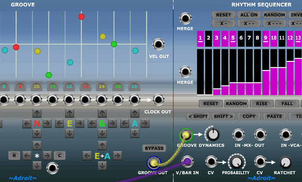
Groove generates 32 timing and velocity adjustment control signals that are passed via a single S-Poly connection linking the module’s GROOVE OUT socket to the GROOVE input socket of Adroit modules that are Groove signal-aware such as the Rhythm and Drum Sequencers.
Multiple sequencers can be controlled by a single Groove module. So a consistent groove can easily be applied to an entire composition. Alternatively, multiple Groove modules may be deployed in order to apply different grooves to different layers or to create changes in groove over time.
If a large number of sequencers need to be connected to the same Groove module then Voltage Modular’s Bus connection system can be used to simplify the wiring and reduce clutter.
The timing adjustment resolution is 1/512th of a bar, in other words each 1/16th note is divided into 32 sub-steps.
Note that for the dynamics aspect of this module to have any impact the sound producing elements of a patch need to respond to the VEL OUT signal of connected Rhythm Sequencers (or the Groove module’s own VEL OUT signal).
Basic operation
Although the notions of time and velocity adjustment are easy to understand, this is quite a complex module as the goal is to provide as much power, freedom and fine-tuned control to the groove designer as is possible.
It’s recommended that you become familiar with the Song Control, Song Part, Rhythm Sequencer and Drum Sequencer modules before experimenting with the Groove module.
Like so many LSSP modules, Groove is driven by a V/Bar signal.
In a basic setup this V/Bar signal would be provided by patching the GLOBAL V/BAR OUT socket from a Song Control Module to the Groove module’s V/BAR IN socket.
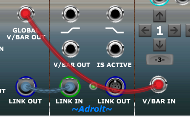
This connection will activate the module and enable you to use its CLOCK OUT, VEL OUT and individual step gate/trigger outputs to drive conventional modules in a variety of useful ways.
Groove’s main purpose though is to modify how Adroit Rhythm Sequencers and Drum Sequencers operate. This is done by connecting a Groove module’s GROOVE OUT socket to the GROOVE input socket of a sequencer.
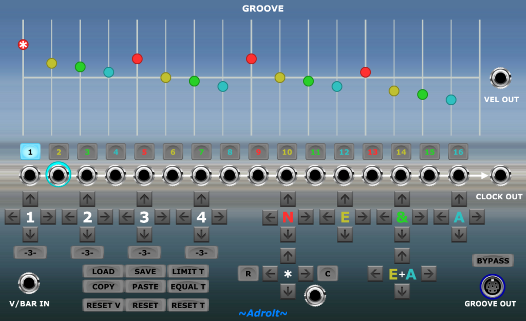
At the top of the Groove module there’s a grid where the horizontal axis represents time and the vertical axis represents velocity.
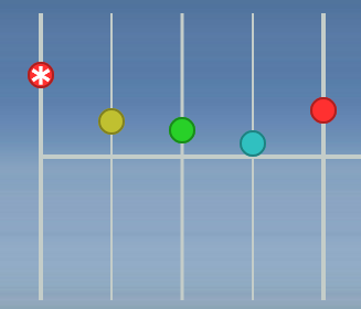
Color-coded circles called “control points” represent the start time and velocity offsets of individual sequencing steps.
The horizontal white line represents a neutral velocity value. The vertical white lines represent time divisions in a regular 16 step pattern.
The Groove module has no effect on timing or dynamics when the control points are exactly aligned on these white lines.
Velocity adjustments can be made by dragging the colored control points up and down or simply by drawing a shape while holding down the left mouse button.
Drawing velocity shapes while a sequence is playing gives you powerful real-time control. The groove’s dynamics can be altered radically with a simple gesture in the blink of an eye. This technique is great for improvisation and can also reveal hidden potential in an otherwise mundane repetitive loop.
Individual steps can be selected by clicking on the colored control points.
Individual steps can also be selected using the row of buttons below the grid. This becomes important when groove timing is heavily manipulated because some control points can disappear. This happens when the duration of a step occupies zero time (this is called “step collapse”).

The currently selected step is called the star (*) step and can be edited using the controls around the * label.
Below the step selection buttons there is a row of sockets that provide an individual gate/trigger output for each step. This makes it easy to do simple low-level rhythm programming. For instance if you want a snare to fire on step 9 you can just patch a cable from the 9th socket to the trigger input of a snare drum module.

The CLOCK OUT socket combines all of these gates to provide a signal that can be used as the clock input for a conventional sequencer. The pulses from CLOCK OUT incorporate all of the micro-timing adjustments so that conventional clock-based sequencers can mirror the micro-timing of any Adroit sequencers using the GROOVE OUT signal.

The VEL OUT socket provides a 0 to 5 volt signal that tracks the velocity offset of each step. The half-way default velocity (indicated by the horizontal white line on the grid) equates to a 2.5 volt output.

The VEL OUT signal is provided to allow modules other than Adroit Rhythm and Drum Sequencers to access the dynamics information.
The Groove module’s VEL OUT signal is just a standard CV signal and can be used for any modulation purpose. It should be noted that CV Sequencer doesn’t have a GROOVE input feature so if you need something like CV Sequencer functionality with timing that does match a groove then you can utilise a Groove module’s VEL OUT for this purpose.
Rhythm Sequencers connected to a Groove module combine their own velocity sequencing information with the velocity offsets from the Groove module according to the DYNAMICS control setting of each Rhythm Sequencer to provide a combined signal via their VEL OUT socket. This enables you to control global dynamics via Groove module settings but modify these at a local level by adjusting the velocities of individual Rhythm Sequencers.
Groups and timing
Below the gate output sockets there’s an array of buttons that provide precise control over the timing and velocity offsets for various groups of steps.
This grouping allows you to make coordinated modifications that would be tedious if done at the level of individual steps.
The up buttons increase the velocity, the down buttons decrease the velocity. The left buttons move steps earlier in time, the right buttons move steps later in time.
The controls on the left arranged around the labels 1, 2, 3 and 4 provide a means of adjusting the velocity and timing of all sub-beats within a main beat simultaneously.

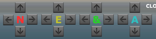
The controls on the right arranged around the labels N, E, & and A provide a means of adjusting the velocity and timing of a sub-beat within all main beats simultaneously.
This will all become clear as soon as you use the buttons because immediate visual feedback is provided by movements of the control points on the screen.
The controls arranged around the label E+A provide a means of adjusting the velocity and timing of the second and fourth sub-beat within all main beats simultaneously. This makes it easy to adjust 16th note swing (using a single button to change eight control points at once).

Timing in Groove uses the same terminology employed by many professional musicians when they discuss rhythm. So the main beats are 1-2-3-4 when there are four beats to a bar or 1-2-3 when there are three beats to a bar.
The sub-beats are N-E-&-A. If you say this out loud it’s “en” “eee” “and” “a”.
The N refers to the main beat – so 1, 2, 3 or 4.
So the way to describe a bar with 16 steps of 1/16th notes is 1, E, &, A; 2, E, &, A; 3, E, &, A; 4, E, &, A. If you say this out loud while clapping your hands or tapping a foot it will make more sense.
If a drummer talks about accenting the 3E they mean making the second sub-beat of the third main beat (i.e. step 10) louder.
Star (*)
The controls clustered around the * symbol provide detailed control over the currently selected step. The socket provides a gate/trigger output reflecting the state of the currently selected step. Connecting this “Star Gate” output to the trigger input of a drum module can be helpful when trying to study the inner workings of a complex groove.
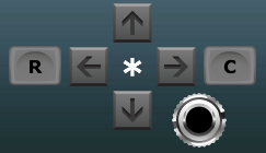
The shortcut button labelled C (for Collapse) on the right of this * cluster moves the selected control point all the way to the same time as the next control point. This causes the selected step to collapse.
It is recommended that you start by making simple dynamics adjustments, then move on to simple timing adjustments and only then begin to explore step collapse. This means that to begin with you might want to leave the LIMIT T button engaged and not use the -3-, C and R buttons until you are more familiar with the core functionality of the module.
The shortcut button labelled R (for Regenerate) on the left of the * cluster moves a collapsed control point to the mid-way point between the adjacent steps. This enables a collapsed step to be quickly regenerated providing that it isn’t hemmed in by another earlier collapsed step.
Collapsed steps
The gate and velocity controls for a collapsed step on an attached Rhythm Sequencer become transparent. The controls can still be changed but they have no impact on the Rhythm Sequencer’s output.

A Melody Sequencer doesn’t know about collapsed steps, it simply keeps stepping through the same sequence of pitches even though a step collapse may have caused the rhythm to change dramatically.
This is one aspect of the disentanglement concept briefly discussed in the design philosophy page.
The control points for collapsed steps disappear as they no longer have any impact on the rhythm and are in any case likely to obscure or be obscured by other control points. The step selection button of a collapsed step has a black outline to make it a little clearer what is going on.

One way to think of a collapsed step is as it being a “black hole” – a timing singularity.
When the LIMIT T button is disengaged then the left and right arrow buttons of the * cluster allow the selected control point to move beyond the confines of its neighboring control points. This creates step collapse rather like a black hole devouring anything it touches.
One simple application of this is if you wish to create a sequence with less than 16 steps. If you want to have say 10 steps then you can select step 11 and then use the * right arrow button to move the 11th step all the way to the right. Then a click on the EQUAL T button will redistribute the surviving 10 steps equally across the bar.
Alternatively individual steps can be collapsed by selecting the control point and using the C button. This enables you to choose which steps to collapse so that the labels of the grouping buttons might still make sense.
The LOAD and SAVE feature described below allows you to save templates so that commonly used patterns can be called up quickly when needed rather than you having to recreate them over and over.
Triplet buttons
The buttons labelled -3- beneath each of the main beat controls automatically convert the four sub-beats inside the associated main beat into three sub-beats by collapsing the fourth sub-beat and evenly spacing the second and third (in other words they convert N-E-&-A into N-E-&). This makes it easy to create certain kinds of triplet rhythms.

For an instant jazz swing feel click on all four of the -3- buttons to convert any connected Rhythm Sequencers to a 12 step pattern that still has four beats to the bar.
This is subtly different to when Song Control is set to 3 BEATS PER BAR. Even though in both cases there are 12 steps, in one situation it’s 4 main beats each with 3 sub-beats and the other it’s 3 main beats each with 4 sub-beats.
Utility functions
The group of buttons in the bottom left of the module provide various handy utility functions.

LOAD and SAVE enable the groove information to be imported from and exported to standard MIDI files. This allows you to build up a library of reusable templates and also to exchange grooves between LSSP and a DAW.
COPY and PASTE transfer groove information between a clipboard and a Groove module. This allows grooves to be quickly copied from one Groove module to another.
RESET V resets just the velocity information to the default neutral state.
RESET T resets just the timing information to the default neutral state.
RESET resets both the velocity and timing information.
The LIMIT T latching button is provided as a safety measure that allows you to alter timing via the * left and * right buttons without accidentally causing a step collapse or altering the timing of neighboring steps.
When LIMIT T is disengaged you can move a single control point earlier or later anywhere in the grid and it will collapse and/or adjust neighboring steps, but this radical change might not be your intention most of the time so the LIMIT T button is engaged by default.
The EQUAL T button identifies all non-collapsed steps and then evenly distributes time between these steps. So if you want to program rhythms with say 14 steps per bar you can collapse two steps and then click on EQUAL T to create a groove that has 14 equally spaced steps.
When dealing with odd time signatures you can choose which steps to collapse – which is often useful for grouping control and also visually (on both Groove and Rhythm Sequencer user interfaces) but ultimately it doesn’t matter which steps you collapse. If you are dealing with complex polyrhythms then it might make most sense to collapse steps at the end of the sequence, click on EQUAL T and then ignore the colors and grouping altogether.
The above might seem rather complicated but after a bit of experimentation it should all make sense. It gives you total freedom over timing yet enables everything to be done in a highly controllable fashion.
Simply being able to drag control points left and right might seem like an easier solution but when this was tried out during prototyping it quickly became apparent that this simple approach just made it extremely easy to make a total mess of things.
It’s still possible to make a mess but usually one or two clicks on Voltage Modular’s Undo button will rescue you. If you ever get totally confused by step collapsing then click on RESET T and start afresh.
Bypass
The BYPASS button above the GROOVE OUT socket disables the effect of the Groove module on connected sequencers when it is engaged.

This module can totally mangle timing and dynamics when required but often the effect you are trying to achieve might be rather subtle so it is useful to be able to do an A/B comparison between groove and non-groove just by clicking on a single button.
The BYPASS button only affects the S-Poly signal output by GROOVE OUT. The user interface and all the other outputs will continue to operate as before.