Table of Contents
Introduction
Please note this documentation is for a new version that will be released in a few days time. The main change is an improvement in velocity handling so most of this new documentation still applies to the old version.
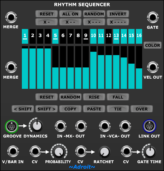
The Rhythm Sequencer module focuses on the creation of rhythmical patterns and provides standard gate and velocity control outputs that will interface with regular modules.
The module’s LINK OUT socket enables it (and optionally a second Rhythm Sequencer) to cooperate closely with an Adroit Melody Sequencer. Indeed the Melody Sequence module requires at least one Rhythm Sequencer to be connected in order to operate.
Although the Rhythm Sequencer will happily generate drum patterns, LSSP includes a more specialised Drum Sequencer that addresses the particular demands of drum programming. The Rhythm Sequencer is more useful for detailed organic rhythm programming where things like velocity and gate length are important.
The Rhythm Sequencer allows for voltage control of the probability of gate firing, ratcheting (repeats of notes) and gate duration. This voltage control can be done synchronously so that it’s possible to control the probability, ratcheting and gate duration of each step independently.
Ties between adjacent steps and over bar boundaries are also supported.
Note there is some subtle complexity to this module so in addition to this overview there is a Rhythm Sequencer Operation page that is more tutorial in style and goes into greater detail.
As with all LSSP sequencers timing is voltage controlled so there is no clock input. The V/BAR IN socket receives a voltage controlled time signal from the Song Control Sequencer or a Time Splitting module (or some other CV source for more experimental applications). See V/Bar for more detail.

Generally the Rhythm Sequencer operates over a one bar period but this can be altered to anything from a 1/99th note to 99 bars by processing the V/Bar signal with a Time Flow Changer module.
Sequence lengths can be extended indefinitely by chaining Rhythm Sequencers together using the Song Control Sequencer, Time Splitters and the MERGE sockets.
When used in combination with the Adroit Groove module you can systematically adjust the velocity and timing of each step in a rhythm – transforming clockwork into something that really feels alive.
The sequencer has 16 steps when Song Control is set to 4 beats/bar and 12 steps when Song Control is set to 3 beats/bar. So there are generally always 4 steps per beat.
However, when connected to a Groove module, radical timing adjustments can be made to the point where steps can be made to collapse and disappear. So it is possible to have any number of steps up to 16 with the duration of each step varying from nothing to the entire sequence length. In other words you have complete freedom to set the boundaries between steps anywhere you like in time.
The GATE OUT socket transmits the current gate value in the sequence.
The VEL OUT socket transmits the current velocity value in the sequence. You can of course choose not to use the VEL OUT signal or use it for something other than amplitude control – controlling the cutoff frequency of a VCF for example.
Gate Pattern
Use the numbered buttons to program the on/off gate pattern.

Individual buttons can be switched on or off with a left mouse click but if you hold down the mouse button and swipe left or right it’s possible to change multiple button states in one swift operation.
The TIE button effects how the gate pattern is interpreted. When it is disengaged each step is independent. When the TIE button is engaged then adjacent steps with gate buttons that are on are joined together to form a sustained note. This can have major impact on rhythms so we’ll look at this in detail on the Rhythm Sequencer Operation page.
Helpful shortcut function buttons at the top can be used to create a convenient starting point…

RESET turns all steps off.
ALL ON turns all steps on.
RANDOM sets a random pattern.
INVERT turns steps that are off on and vice versa.
X – sets every odd numbered step on.
X – – sets every third step on.
X – – – sets every fourth step on.
X – – – – sets every fifth step on.
Velocity Settings
The colored bars below the numbered gate buttons show the velocity for each step.

Use the mouse to alter the velocities. You can hold down the left mouse button and quickly “draw” shapes or you can click on individual bars to change just one step.
A right click copies the velocity of the previous step to the step being clicked on. You can also hold down the right mouse button to quickly swipe right across a number of steps so that they all end up sharing the same velocity value.
You’ll notice that the exact behavior of the velocity bars depends on the current gate pattern (and whether the TIE button is engaged). This is because velocity is determined at the onset of a note.
When the gate button for a particular step is not engaged the velocity of that step is determined by the velocity of an earlier step.
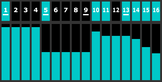
So in the image above steps 2, 3 and 4 have the velocity of step 1; steps 6, 7, 8 and 9 have the velocity of step 5 and step 12 has the velocity of step 11.
This is with the TIE button disengaged. If the TIE button was engaged then step 11 would have the velocity of step 10 and steps 14, 15 and 16 would have the velocity of step 13.
Again we’ll look at this in detail on the Rhythm Sequencer Operation page.
Directly below the velocity bars there’s a bank of shortcut function buttons that change the velocities…

RESET sets all velocities to the default 75% value.
RANDOM sets the velocities to random values.
RISE sets the velocities in increasing order to create a crescendo effect.
FALL sets the velocities in decreasing order to create a decrescendo effect.
Other Functions
The COLOR button lets you to pick a color for the gate buttons and velocity bars. This can be useful in large patches where color coding can help you identify related sequencers. Or perhaps you just have a favorite color.

Four buttons beneath the velocity shortcuts affect the entire pattern – both gates and velocities.

< SHIFT shifts the pattern one step to the left (earlier in time), rotating the first step to the last.
SHIFT > shifts the pattern one step to the right (later in time), rotating the last step to the first.
The COPY and PASTE buttons allow you to copy data from one Rhythm Sequencer to another – handy for quickly creating subtle variations from bar to bar. Click on COPY to copy the pattern to the clipboard. Click on PASTE to copy a pattern from the clipboard to the current module.
Tie and Over Buttons
When the TIE button is engaged adjacent steps with gates that are on are joined together to form a sustained note. This can have quite a profound impact on rhythms so it’s worth spending some time figuring out how this button changes things.

Generally when programming drums or very fast melodies one would set TIE off so that sixteenth note rhythms are preserved, but otherwise setting TIE on allows for the natural programming of varying note lengths.
When the TIE button is engaged velocities for tied steps are locked together as one would expect.
The TIE function is applied to the whole gate pattern so it’s not possible to mix tied and untied notes in one sequencer. The workaround should for you want to work with both 1/16 notes and tied notes is to chain two Rhythm Sequencers together and use Time Flow Changer to run them at double speed. This will give you 32 steps per bar (or 24 if Song Control is set at 3 beats/bar). You can then have TIE enagaged while still being able to use 1/16 notes.
When the OVER button is engaged the very last step is tied over to the next bar. This enables notes to span bar boundaries and also allows sustained notes that last for several bars to be programmed.
Groove
The GROOVE input socket takes signals from an Adroit Groove module enabling systematic micro-timing and dynamics adjustments to be made to each step.

The DYNAMICS knob enables you to adjust the effect of the groove on the module’s velocities. At minimum setting the module ignores groove dynamics completely. At the default (12 o’clock) setting groove dynamics have a normal effect. At maximum setting groove dynamics have twice the normal effect on velocities.
Probability
The PROBABILITY knob sets the probability of a gate firing. This defaults to 100%. The CV input socket to the left of the knob enables the probability to be voltage controlled.

When a signal is connected to the CV input the knob controls the minimum probability (i.e. when the control voltage is at zero volts). So when the knob is set at maximum the control voltage has no effect.
As well as offering useful adjustment to a modulating signal this allows a gate to be used to override the probability set by the knob. When the CV input is 5 volts the probability will be 100% and the knob has no effect. When the CV input is 0 volts the probability will be set by the knob.
Note that it is possible to completely turn off gate outputs with a zero probability setting. Something to watch out for if a Rhythm Sequencer appears not to be working is that the PROBABILITY setting is accidentally set at zero.
Ratcheting
The RATCHET knob sets the number of repeats of a step. This defaults to 1. The maximum value is 6. The CV input socket to the left of the knob enables the ratchet setting to be voltage controlled.

When a signal is connected to the CV input the knob controls the maximum number of repeats (i.e. when the control voltage is 5 volts or above). So when the knob is set at minimum the control voltage has no effect.
As well as offering useful adjustment to a modulating signal this allows a gate to be used as input. When the gate is high the ratcheting will be the number of repeats set by the knob. When the gate is low a single gate will result.
Note that ratcheting is applied to individual steps rather than tied notes and as there are usually 16 or 12 steps per bar then ratching produces very short gate events. For instance a ratchet of 2 will produce 1/32 notes when the Song Control module is set to 4 beats/bar.
Gate Time
The GATE TIME knob sets the duration of the gate. This defaults to 50% of the step duration. The CV input socket to the left of the knob enables the gate time to be voltage controlled.
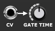
When a signal is connected to the CV input the knob adds an offset to the input. This enables the range of the effect to be adjusted. The exact result depends on whether the input is unipolar (perhaps the output of a sequencer or an envelope generator) or bipolar (as produced by a typical LFO).
When a step is ratcheted then the GATE TIME controls the proportion of the repeated note rather than the entire step. So if ratcheting is set at 2 a gate time setting of 50% means that each of the two gate pulses last 25% of the length of the step.
Modulation
The CV input sockets enable you to modulate probability, ratcheting and gate time using things like LFOs and envelope generators but a another very useful technique is using a synchronized sequencer to control these parameters independently for each step.
One easy way to explore this is to patch the VEL OUT socket of a Rhythm Sequencer back into any of its own CV in sockets. Then you can use the velocity bars to control the probability, ratcheting or gate time of each step.
Mutual Exclusion
The MX IN and MX OUT sockets enable special signals to be passed between Rhythm Sequencers to automate Mutual eXclusion so that two Rhythm Sequencers do not have a gate on at the same step.

To link two Rhythm Sequencers for mutual exclusion, patch the MX OUT of each sequencer to the MX IN socket of the other as shown below.
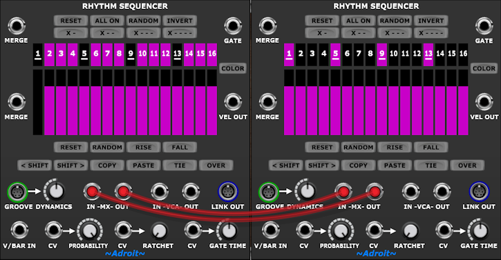
When wired together like this, setting a step’s gate on in one sequencer automatically switches off that step’s gate in the other sequencer.
Built-in VCA
The VEL OUT signal also controls the gain of a handy built-in voltage controlled amplifier (VCA). This enables you to change the volume of a signal with the velocity without having to use a separate VCA,

A few milliseconds of slew is applied to changes in the VCA’s gain to soften the impact of abrupt changes in velocity and reduce popping sounds that might arise in certain circumstances. This slew doesn’t affect the VEL OUT control voltage.
Three beats per bar operation
To support 3/4 and related time signatures Song Control provides an option to switch from 4 beats per bar to 3 beats per bar.
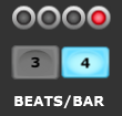
Using three beats per bar has serious consequences for a 16 step sequencer because 16 is not a multiple of 3. Therefore when Song Control is set to 3 beats per bar the number of steps available in Rhythm Sequencer automatically adjusts to 12 – which is a multiple of 3.
This means that one beat corresponds to four Rhythm Sequencer steps whether working in 3/4 or 4/4 related time signatures.
When using the Groove module this may not actually be the case as Groove enables the timing of steps to be radically altered – to the point where steps can be “collapsed” (i.e. made to disappear). This allows you to create rhythms that use things like triplets and unconventional time signatures.
As it’s not often that 3/4 time is used in modular synthesizer genres, a text message saying “12 STEPS WHEN 3 BEATS/BAR” pops up where the missing controls would be. It may be that you have three beats per bar selected accidentally.
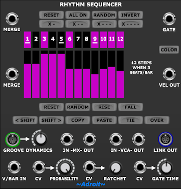
Should you end up in a situation when building a new patch where Rhythm Sequencer is “stuck” in 3 beats per bar mode and you do not wish to use Song Control in the patch, then load up Song Control anyway, click on its 4 BEATS/BAR button then remove it from the patch.
Collapsed Steps
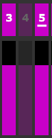
When a Rhythm Sequencer is connected to a Groove module then the timing of steps can be manipulated up to the point where steps can occupy zero duration. This is called “Step Collapse” and when this happens such steps become transparent in Rhythm Sequencer to show that they no longer have any impact on velocity, gate signals or ties.
See the Groove module documentation for more information.
Availability
The Rhythm Sequencer module is available in both LSSP XL and LSSP 101.