V/Bar (meaning Volt Per Bar and pronounced VEEBAR) is a standard used by all LSSP sequencer modules. It uses voltage as an analog of time just like V/Octave uses voltage as an analog of pitch.
V/Bar sequencing has several advantages over conventional clock-based sequencing (which uses a regular pulse to represent the advance of time).
V/Bar is conceptually simple, flexible, fault-tolerant and has sample-level timing precision.
The V/Bar standard uses one volt to represent one bar (measure). This means that a quarter note duration is represented by a 1/4 of a volt difference. Eight bars is an 8 volt difference. In a song the beginning of the 12th bar will be represented by 12 volts.
In a long song the voltage available at the GLOBAL V/BAR OUT socket of the Song Control module might get higher than 100 “volts” but there is no danger of electrocution! Because voltages inside Voltage Modular are just floating point numbers represented in binary they are not limited like an actual voltage would be. Even though the standard voltage range is -5 volts to +5 volts, in practice having voltages outside this range doesn’t cause any problems.
Although Song Control’s GLOBAL V/BAR OUT signal is quite useful in itself, more often LSSP patches use lower voltage V/Bar signals that are derived from it using something called “time splitting” which will be discussed shortly.
V/Bar sequencers do not have any internal count state. This “statelessness” results in simplified wiring as they do not need reset, start or stop signals and sequencer behaviour is far more reliable than in a clock-based system. For instance while a V/Bar sequencer is running you can unplug a cable carrying its V/Bar signal and then plug it back in any time later and the sequencer will instantly jump to the correct time. This “self-healing” ability is very useful when working on large patches that contain dozens of sequencers.
Something like V/Bar probably wouldn’t work well in analog hardware as in practice the voltages would need to be scaled down significantly and noise caused by things like dirty patchchords might become an issue., but Voltage Modular has a signal to noise ratio of at least 318 dB so noise is not a problem. As Mark Barton points out Voltage Modular is about 89 billion times more accurate than Eurorack.
Note that as time in LSSP is just a voltage/number it can be operated on with simple arithmetic. Addition moves time forwards, subtraction moves time backwards. Multiplication makes time flow faster, division makes time flow more slowly.
Table of Contents
Song Control Sequencer
Almost all LSSP patches will have a Song Control module along with at least one Song Part module forming a combination called a Song Control Sequencer.
Song Part modules represent individual parts of a song such as an intro, verse, break, outro and so on and any number of them can be chained together to build songs of whatever length is required.

The V/Bar outputs from these modules control V/Bar sequencers either directly or via V/Bar Routers and/or V/Bar processors.
V/Bar Sequencers
All V/Bar sequencers have a V/Bar input socket that is fed a voltage that controls their current position in the sequence. Because they don’t have any internal memory of their position there’s no need for reset inputs.
As well as signifying position by voltage, the V/Bar standard provides a simple mechanism for switching sequencers on and off. If zero volts is fed to a sequencer’s V/Bar input it will be disabled. There’s no need for V/Bar sequencers to have start or stop control inputs and large numbers of sequencers, perhaps configured in long chains, can cooperate – with control passing from one sequencer to another as required in a computationally efficient manner.
Generally V/Bar sequencers output zero volts when disabled so chains of sequencers that operate in turn can have their outputs combined simply by patching all their outputs together – no switching mechanism is required. However MERGE input sockets can be used to keep help keep wiring tidier and make sequencer chaining more obvious. When a V/Bar sequencer is disabled it will pass its merge input to its output.

Most but not all V/Bar sequencers handle a single bar (usually divided into 12 or 16 steps) so their V/Bar range begins at 1 volt and ends at just short of 2 volts. V/Bar voltages of 2 volts or higher cause a simple wrap around so that the sequence repeats when higher voltages are used.
When Song Control is in 4 beats per bar mode most sequencers have 16 steps so a 1/16 volt change maps to a change of 1 step. When Song Control is in 3 beats per bar mode most sequencers have 12 steps so a 1/12 volt change maps to a change of 1 step.
Current V/Bar sequencers in LSSP are…
CV Sequencer – a dual channel general purpose 16 step CV sequencer.
Rhythm Sequencer – a 16 or 12 step gate and velocity sequencer.
Drum Sequencer – an 8 channel 16 or 12 step gate/trigger sequencer.
Melody Sequencer – a 32 step sequencer specialized for handling melodies. It doesn’t have its own V/Bar input, instead it is controlled by one or two Rhythm Sequencers.
Progression – a 16 step step sequencer specialized for handling chord progressions.
Groove – a 16 or 12 step sequencer specialized for handling micro-timing and systemic velocity.
Beats – a simple sequencer with 16 different trigger outputs that fire at rates from once per bar to 16 times per bar.
Triggers – another simple sequencer that divides a bar up into 16 steps and has a separate trigger output for each step.
V/Bar Routers
In large projects the wiring between Song Part modules and V/Bar Sequencers can get messy so at a certain scale it makes sense to use Router and Router Outputs modules to manage the wiring.
V/Bar Processors
V/Bar processors take a V/Bar signal as input, does some processing on it and produces one or more related V/Bar signals as outputs.
Time Splitters are an important subcategory of V/Bar processors which we’ll look at shortly.
Beyond Time Splitters there are three V/Bar processors…
Time Flow Changer – this module allows us to make precise changes in time flow rates in oder to speed up or slow down sequencers.
Time Cycle Changer – allows us to reduce the number of steps that a V/Bar sequencer uses making it easier to create polymeteric sequencing and time divisions based on numbers such as 5, 7 or 9.
Time Changer – essentially a Time Flow Changer and Time Cycle Changer wired in series that makes polyrhythmic sequencing very straightforward.
Time splitting
An important concept in LSSP is the idea of “splitting time”. This involves taking a V/Bar signal and distributing it to different parts of a patch depending on the voltage. It’s key to sequencer chaining.
The simplest Time Splitter is a module called Time Split 2. It takes a V/Bar input signal and splits it into two output signals – one for odd numbered bars and another for even numbered bars.

To understand how time splitting works in practice let’s use the CV Watcher module to look at the V/Bar signals from Time Split 2…
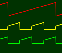
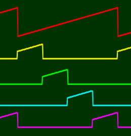
The red trace shows the V/BAR IN input voltage varying from 1 to just short of 4 volts over a period of four bars.
The yellow trace shows the signal output by Time Split 2’s ODD BARS output socket.
The green trace shows the signal output by Time Split 2’s EVEN BARS output socket.
The bottom two traces show how the module splits time into two parts. Each output can then be used to drive a separate V/Bar sequencer for a single bar at a time. Notice how the voltage for one output drops to zero when the other output is active.
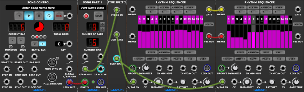
The image below shows how a Time Split 2 module can be used to chain two Rhythm Sequencers together in order to create a 32 step sequence that has a two bar cycle.
The Time Split 4 module splits time into four bars.
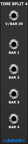
The Time Split 4 traces below show how the time splitting principle can be extended to four outputs that could control four sequencers over four bars.
Time Splitters aren’t confined to splitting single bars. The Time Split Fills module for instance provides four time splitters that handle fills of various lengths. These make it easy to use one sequence over a certain number of bars and then change to a different sequence for the last bar.
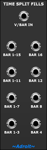
The CV Watcher traces below show the BAR 1-3 and BAR 4 outputs in action.
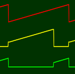
As before the red trace shows the input voltage rising over four bars. The yellow trace shows the BAR 1-3 output and the green trace shows the BAR 4 output. Notice how the yellow BAR 1-3 trace goes from one to just short of three volts over the first three bars and then gives way to the other output for the final bar in every four bar loop.
Note that Song Part modules are in effect specialised types of time splitters with user selectable rather than hard wired numbers of bars.
Why?
In a simple LSSP patch the V/BAR OUT sockets of Song Part modules might be directly connected to sequencer V/BAR IN sockets. But you have the freedom to add multiple layers of intermediate time splitting modules so that you can work at the level of “form” – creating non-linear patterns that reuse motifs.
For instance a song part might last 16 bars. You could have one element of the patch repeating the same behaviour for every single bar. Another element might play seven bars the same and then change for a fill in the last bar of an eight bar cycle. Another element of the patch might follow an ABAC form over a four bar cycle. In parallel you might have a 16 bar long chord progression happening that modifies the pitch quantization of the repeating melodic sequences so that even a relatively small number of sequencers can produce music that goes on a satisfying harmonic journey.
This all sounds rather abstract so let’s look how the above might work in practice…
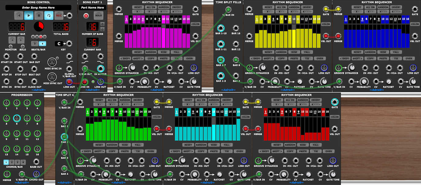
For reasons of space and clarity this is only a partial patch that simply drives six Rhythm Sequencers and a Progression module (there is no sound generation or control of pitch). But it demonstrates the V/Bar sequencing described above. The V/Bar signals are being carried by the green cables.
The Rhythm Sequencers are color coded…
The magenta one repeats the same pattern every bar.
The yellow one plays for seven bars then gives way to the blue one.
The ABAC form is implemented by the three Rhythm Sequencers at the bottom. Green is A, cyan is B and red is C.
The Progression module in the bottom left performs one cycle over the entire 16 bars, changing chord at a rate of one chord per bar. No actual chords are plugged into it in this simple illustration though.
Time splitting modules can be wired together in endless ways to create potentially very complex generative V/Bar sequencing networks. Yet when Song Part modules are at the top of the hierarchy it’s relatively easy to maintain an overall linear time line. So you can indulge in the creative chaos of a generative system while still having the benefit of a well-defined overall song structure.