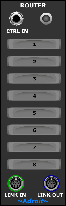
Multiple router modules can be used in conjunction with a Router Outputs module to make complex V/Bar wiring tidier, easier to change and more obvious in intent.
To understand the point of using Routers in LSSP you need to first know about V/Bar and the Song Control and Song Part modules.
Routers are very useful in patches that use a large number of Song Part modules where sequences are reused a lot. There’s not much point in using Router and Router Outputs modules in simple patches where it’s not difficult to trace and modify the V/Bar wiring.
You might never use Routers if your computer isn’t capable of running large scale patches.
Table of Contents
Basic Operation
The image below illustrates the typical relationship between Song Control, Song Part, Router and Router Outputs modules (although in practice there would usually be more Song Parts than shown here),,,
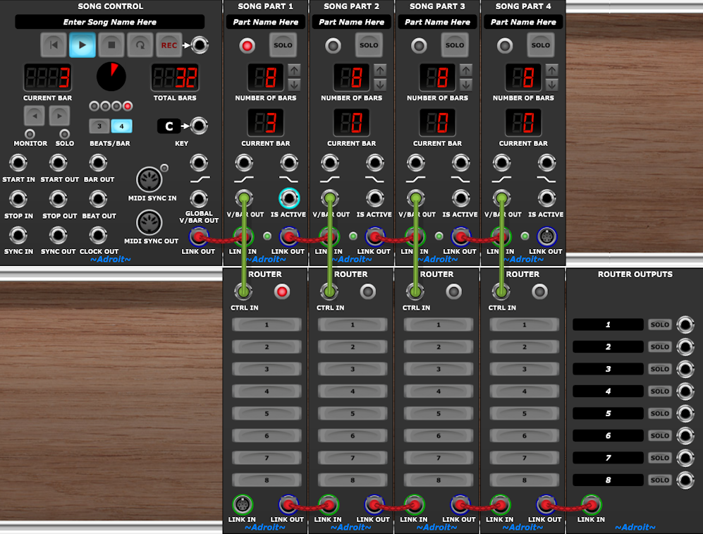
The green cables feed V/Bar signals from each Song Part to a matching Router.
All the Routers are linked together with 8 channel S-Poly connections and the LINK OUT of the last Router in the chain is connected to a Router Outputs module.
The Router module’s functionality is pretty simple. If its CTRL IN socket receives zero volts then it passes the S-Poly signal from its LINK IN socket to its LINK OUT socket but if the CTRL IN signal is not zero volts then the Router inspects its 8 toggle buttons. If a button is engaged the voltage from CTRL IN is sent to the corresponding channel of the LINK OUT socket. If a button is not engaged then zero volts is sent to the corresponding channel.
If a Router module has nothing connected to its LINK IN socket it passes zero volts on all channels to its LINK OUT socket when its CTRL IN socket is fed zero volts.
As only one Song Part can be active at any time then only one Router is active too. An LED lights to show which router is active.
The Router Outputs module takes the 8 channels of voltages from the chain of Routers and sends them to the corresponding mono output sockets while taking into account whether any of the SOLO or MUTE buttons are engaged.
Several SOLO buttons can be engaged at the same time to enable one to listen to sub-mixes. If any SOLO button is engaged then any channel that doesn’t also have its SOLO button engaged is muted by having its output forced to zero volts.
Clicking on an engaged SOLO button disengages it. This will mute that channel if any other SOLO buttons are still engaged.
The MUTE buttons force an output to be zero volts.
If both the SOLO and MUTE buttons are engaged at the same time then the solo function takes precedence.
A Test Rig
The image below shows a little test rig that will hopefully help explain what happens when we engage some of the Router modules’ buttons…
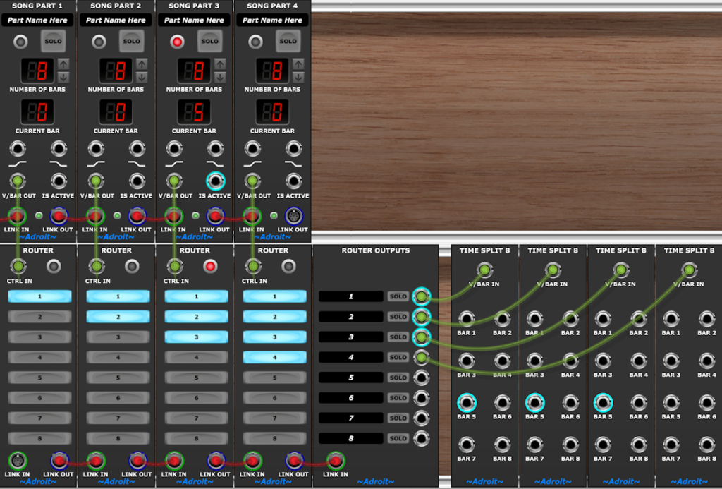
The Time Split 8 modules on the right serve just to show roughly what V/Bar values are being output by the Router Outputs module.
If you look closely at the screenshot you’ll see that the current bar is bar 5 of Song Part 3 and as the Router connected to Song Part 3 has buttons 1, 2 and 3 engaged the outputs 1, 2 and 3 from the Router Outputs module are all V/Bar signals in bar 5. Output 4 is zero volts because button 4 of the Router connected to Song Part 3 is not engaged.
We could achieve the same result without using any routing modules using the following wiring…
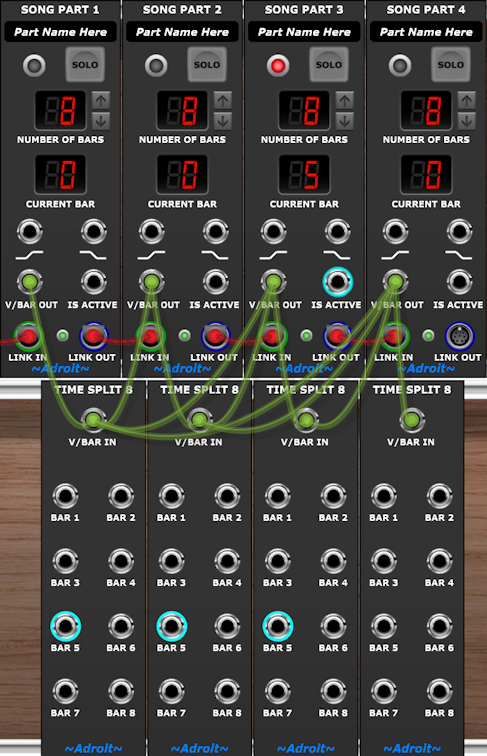
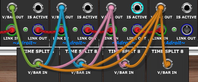
If you check the wiring you’ll see that each engaged button in the router version of the test rig corresponds directly to a cable in the non-router version.
This is still a relatively simple wiring situation and it’s sort of borderline as to whether its worth using routers in this case
Note when not using Routers we could use color-coded cables to makes it easier to trace the wiring either like this…
…or like this…
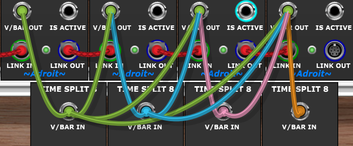
But if you look at the wiring above and compare it with the pattern of illuminated buttons in the Router version hopefully you can see that it’s more obvious what is happening when Routers are used.
In a larger scale patch, one might want to handle a wiring situation like this…

In this case it’s definely worth using Routers because the resulting interface is a neat and logical switch matrix rather than a 41 cable mess that would be extremely difficult to understand or change.
One could think of the interface above as a bit like the view presented by a DAW (with time on the horizontal axis and tracks on the vertical) or as a matrix patchboard (like found on the EMS VCS3) where each engaged button is like an inserted pin.
Remember that the outputs from Router Outputs are the same as the signals coming out of a Song Part’s V/BAR OUT socket – zero volts means a sequence is inactive and non-zero voltages range from 1 volt to a voltage that’s a tiny fraction less than the number of bars set for a particular Song Part’s length.
Expanding Beyond 8 Channels
The basic layout shown in the sub-patches above is limited to 8 channels but you can add extra rows of Routers to expand as needed. For instance to handle 16 channels we can add another row of Routers and another Router Outputs module…
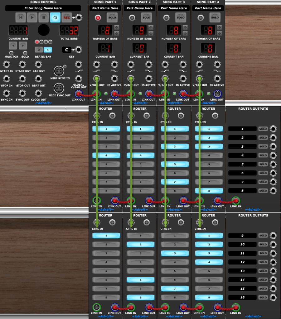
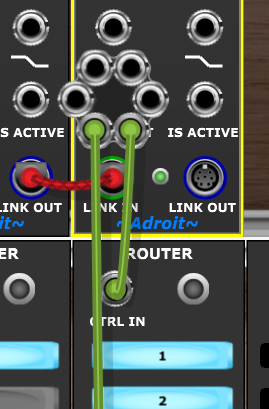
Although the vertical green cables look a bit odd in this screenshot, there are actually two cables attached to each V/BAR OUT socket on the Song Part modules…
Demo Patch
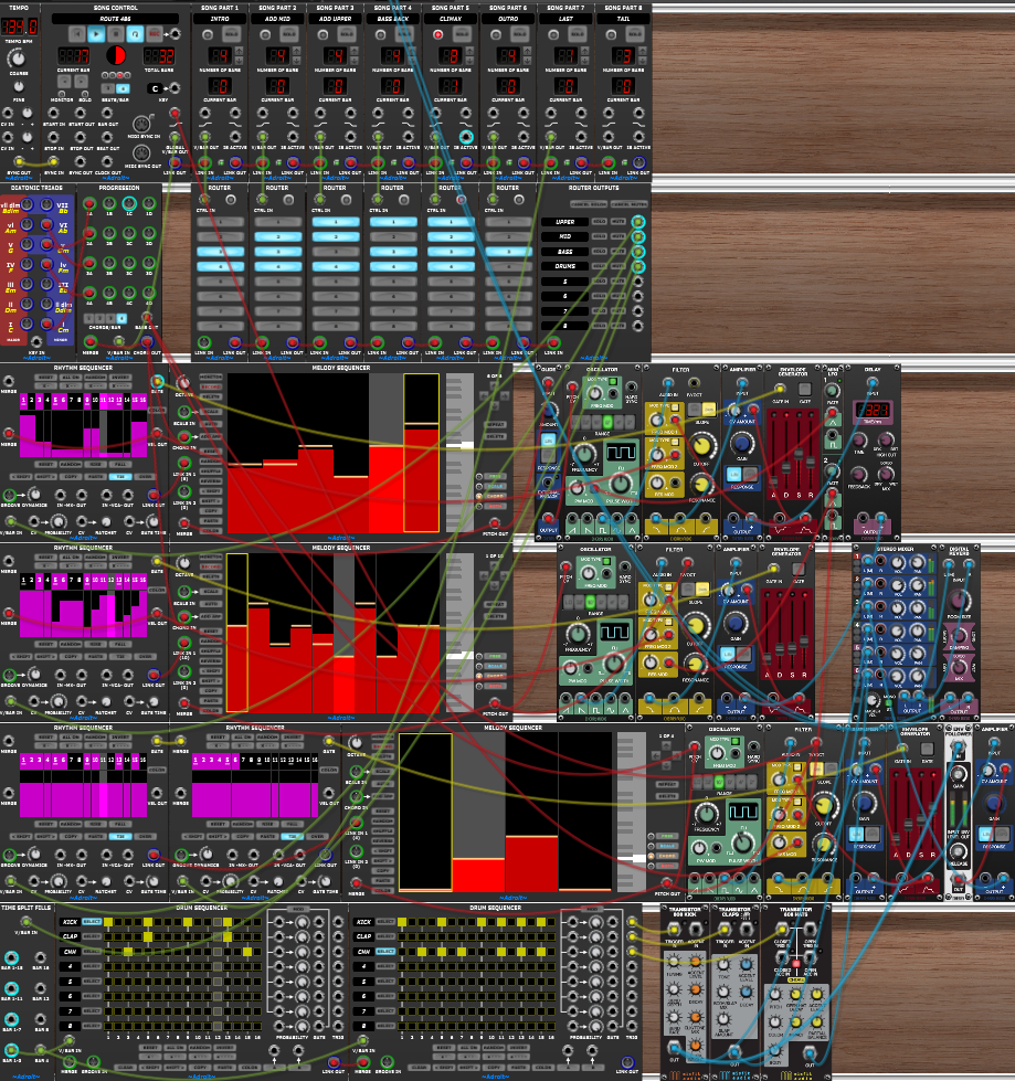
A relatively simple demo patch showing how Router and Router Outputs modules might be used in practice can be downloaded by clicking on the button below.
Open the downloaded .voltagepreset file to automatically launch Voltage Modular with the preset ready built. Then click on the play button of the Song Control module in the top-left corner of the patch to start a simple demo song playing.
Availability
The Router module is only available as part of LSSP XL.