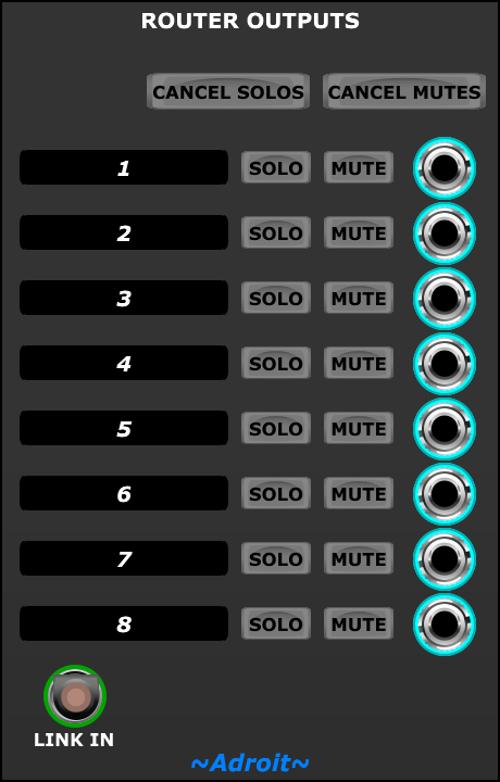
Router Outputs module

This simple module can be used in conjunction with multiple Router modules to make V/Bar wiring tidier and more obvious.

See the Router documentation for a description of the overall routing mechanism. Here, we’ll look at a few details specific to the Router Outputs module and also discuss the issue of merging.

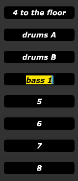
Editable Labels

The areas labelled 1, 2, 3 and so on are editable text fields. Click on them to give meaningful names to the channels
Solo and Mute Buttons

Individual channels can be soloed using their SOLO buttons. The CANCEL SOLOS button cancels all active solos.

Individual channels can be muted using their MUTE buttons. The CANCEL MUTES button cancels all active mutes.

If both the SOLO and MUTE buttons are engaged at the same time then the solo function takes precedence.

When a channel is muted its corresponding output is forced to zero volts which will deactivate any attached V/Bar sequencer(s). This will generally silence any sound producing modules attached but it’s not the same as audio muting. For instance any envelope generator involved will usually go into its decay or release phase so the sound will fade away rather than stop abruptly. In most circumstances this is preferable to audio muting.

V/Bar Muting and Merging

V/Bar sequencers become inactive when fed a zero volt V/Bar signal. This forces their outputs to zero volts. This works fine with gates and triggers driving things like envelope generators as the envelope generators will go into their decay or release phase.

But sequencer CV outputs that affect things like pitch need to hold the last value used otherwise the pitch will fall as notes decay.

Conventional clocked sequencers have an internal position state so they “remember” where they are in time. So when they stop the final value is held. This solves one problem but it means that chaining conventional sequencers is difficult – you can’t just add all their outputs together as the resulting pitch CV would be wrong. So a switching mechanism is required. Also start, stop and reset mechanisms are required to make sure that internal position states keep in sync.

In contrast V/Bar sequencers don’t have an internal position state and their CV outputs can simply be added together because inactive sequencers (those with V/Bar inputs of zero volts) output zero volts. So no switching mechanism is required nor any start/stop or reset mechanisms. But when all V/Bar sequencers in a chain are inactive the output of the chain is wrong (it’s zero volts rather than the last value).

LSSP solves this problem by using MERGE inputs.

At first glance MERGE inputs look like a switching mechanism, but as mentioned above there is no need for any switching as all outputs can simply be added together.

So then it seems like the MERGE inputs are just a way of keeping the wiring tidy as each sequencer in a chain is linked to another in the same chain (although the order of the chaining doesn’t matter) but this is not the main reason for merging either.

Merging provides a fix for the zero volts problem when all sequencers in a chain are inactive.

Although I’ve said that a V/Bar sequencer outputs zero volts when it is fed a zero volts V/Bar signal this isn’t actually always the case. If a cable is plugged into its MERGE IN socket then the MERGE IN signal is passed to the output rather than zero volts.

So the solution to the problem of final values not being held is to patch a cable from the output of the last V/Bar sequencer in the chain back to the MERGE input of the first sequencer in the chain – thus forming a ring.

Then when all sequencers have zero volts V/Bar inputs the last value output is continuously passed around the ring and is thus magically held static until any of the sequencers becomes active again.

If there’s only a single sequencer involved then patch its own output to its own MERGE input.