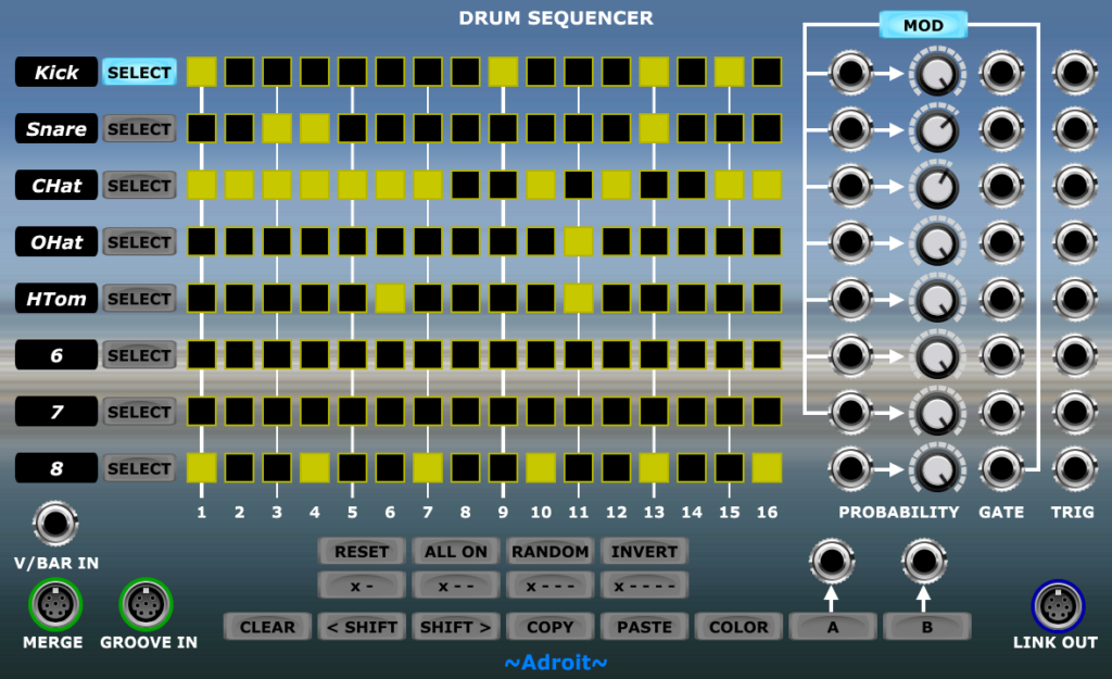
The Drum Sequencer is effectively eight Rhythm Sequencers crammed into one module, although some features of the full-scale Rhythm Sequencer are omitted and the handling of gates is slightly different.
It’s primarily designed to provide a compact solution for programming drum patterns but as its outputs are standard gate and trigger signals it can be used for a wide range of applications.
In addition to this overview there is a Drum Sequencer Operation page that goes into greater detail in a tutorial format.
This module is also showcased in the London Crime Theme LSSP XL workshop.
The core part of the user interface is very similar to the Rhythm Sequencer so you should be able to quickly figure out how to program patterns if you are already familiar with that module.
You may find it it easier if you zoom in when programming patterns although with a little practice the small size of the buttons becomes less of an issue (also note that swiping operations are deliberately limited to one track at a time to help reduce accidents).
As with all Adroit Synthesis sequencers timing is voltage controlled via the V/BAR IN socket so there is no clock input. See V/Bar for more detail.
Generally the Drum Sequencer operates over a one bar period but this can be altered to anything from a 1/99th note to 99 bars by using a Time Flow Changer module.
Sequence lengths can be extended indefinitely using the Song Control Sequencer, Time Splitters and the MERGE socket to chain any number of Drum Sequencers together.
When used in combination with the Adroit Groove module you can systematically adjust the timing of each step.
The sequencer has 16 steps when Song Control is set to 4 beats/bar and 12 steps when Song Control is set to 3 beats/bar. So there are generally always 4 steps per beat.
However, when connected to a Groove module, radical timing adjustments can be made to the point where steps can be made to collapse and disappear. So it is possible to have any number of steps up to 16 with the duration of each step varying from nothing to the entire sequence length. In other words you have complete freedom to set the boundaries between steps anywhere you like in time.

Each of the eight tracks has (from left to right) an editable text label, a SELECT button, sixteen buttons for programming gate patterns, a CV input and knob for controlling PROBABILITY, a GATE output and a TRIGGER output.
Individual gate buttons can be switched on or off with a left mouse click but if you hold down the mouse button and swipe left or right it’s possible to change multiple button states in one swift operation. You do not need to use SELECT to program these buttons, Rather the SELECT button determines which track is affected by the shortcut buttons below the tracks.
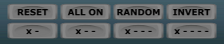
RESET turns all steps off.
ALL ON turns all steps on.
RANDOM sets a random pattern.
INVERT turns steps that are off on and vice versa.
X – sets every odd numbered step on.
X – – sets every third step on.
X – – – sets every fourth step on.
X – – – – sets every fifth step on.
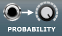
Each track has a PROBABILITY knob and an input socket to its left. The basic functionality is simple – the knob sets the probability of a gate/trigger occurring. However, Drum Sequencer has several neat features when probability is voltage controlled. See Drum Sequencer Operation for more details.
At the bottom of the module beneath the shortcut buttons that only affect the currently selected track there’s a row of function buttons that apply to all eight tracks at once.

CLEAR resets all tracks.
< SHIFT shifts all the patterns one step to the left (earlier in time), rotating the first step to the last.
SHIFT > shifts all the patterns one step to the right (later in time), rotating the last step to the first.
The COPY and PASTE buttons allow you to copy data from one Drum Sequencer to another – handy for quickly creating subtle variations from bar to bar. Click on COPY to copy the pattern to the clipboard. Click on PASTE to copy a pattern from the clipboard to the current module. Note that only the gate pattern data is copied.
COLOR cycles through a choice of colors for the gate buttons so that you can color-code modules.
In the bottom left corner of the module are three input sockets…
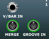
V/BAR IN is fed a V/Bar signal typically from a Song Part module, a Time Splitter or perhaps an AHR Generator.
MERGE is an S-Poly input socket that enables Drum Sequencers to be chained together. It carries eight gate and eight trigger signals from one module to another, potentially saving you having to patch up to 16 cables.
GROOVE IN is an S-Poly input socket that receives an optional groove signal from a Groove module. Obviously as the Drum Sequencer doesn’t handle velocities then only the 16 micro-timing signals are used. Note that each Drum Sequencer can have a different groove if required.
In the bottom right of the module there are a pair of buttons…
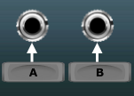
These are simply latching buttons that output either 0 volts or 5 volts to the sockets above them depending on whether they are off or on. You can use these as just general purpose switchable DC sources but their main purpose is when patched to tracks’ PROBABILITY CV inputs. Various applications (including using them to set up mute groups) are discussed on the Drum Sequencer Operation page.
To the right of the A and B buttons is an S-Poly LINK OUT socket.

This is used to transfer all the gate and trigger signals to another Drum Sequencer module’s MERGE input socket when chaining modules together. It can also be fed to the LINK IN socket of a MIDI Drum Kit module in which case the first 6 tracks’ trigger signals are patched to the MIDI Drum Kit channels. It’s simply a mechanism to save on the number of cables used.
Note that the LINK OUT signal is not compatible with the Melody Sequencer. The Melody Sequencer LINK IN sockets must be fed with the LINK OUT signals from Rhythm Sequencers.
In the top right of the module there’s a button labelled MOD (short for modulation).

When MOD is engaged the gate output of Track 8 is routed as shown by the legend to be the default PROBABILITY CV input for Track 1 through 7. This modulation routing is discussed in detail on the Drum Sequencer Operation page.
Availability
The Drum Sequencer module is part of LSSP XL.