Table of Contents
Introduction
This module is dedicated to scene management in the Adroit Custom system.
The presence of a Custom Scene Manager module in a patch expands the capabilities of Custom Panel modules and unlocks hidden options in their right-click menus.
If a Custom Scene Manager module is not present in a patch then Custom Panel modules behave as if scene 1 is selected.

A scene consists of the settings of all the controls in your custom interface. There are 16 scenes available, labelled 1 through 16.
By default, changing scene changes the settings of all of the controls in your custom interface, although you can configure this on a control by control basis if required. Critically, you can not only switch instantly between scenes, you can also smoothly and continuously morph (interpolate) between them. This Scene Morphing can be under manual, sequenced or voltage control.
It’s possible to morph at high speed, so for instance an envelope generator could be used to sweep through a continuum containing multiple scenes in the span of a single note. Or you might want to produce a dreamy ambient piece where morphing is controlled by a very low frequency LFO so that sounds evolve gradually over time. Or you could use things like velocity, aftertouch or the mod wheel to access new forms of expression. Or you might use scenes on a more global scale for managing orchestration or for performing generalized automation. Scene Morphing can also be used for sequencing purposes as in effect there’s an invisible 16-step sequencer hiding behind every Adroit Custom control.
Note that Scene Morphing is quite different to Vector Synthesis. Vector Synthesis merely changes the mix levels of various sound sources while Scene Morphing allows every parameter in your patch to be in motion. As a simple example, consider using an LFO to modulate pitch to produce a vibrato effect. In Vector Synthesis one can cross-fade between a sound that has slow vibrato and a sound that has fast vibrato but with Scene Morphing the actual LFO rate can change smoothly instead.
Although scenes might seem similar to Voltage Modular variations there are significant differences. Scenes support morphing, have a well-ordered and deliberately limited structure and only directly affect Custom Panel controls. Regular Voltage Modular controls are only affected by scenes if they are being remotely controlled by Custom Panel controls.
It is possible to use scenes and variations at the same time but it is strongly recommended that you avoid this until you have a full grasp of how both scenes and variations work. Technically there are 16 scenes inside each variation.
Basic Operation
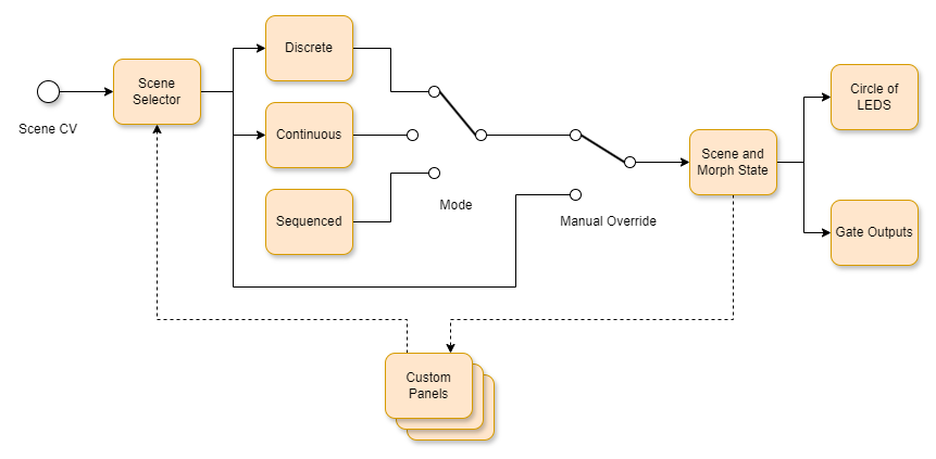
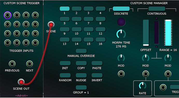
At the top of the Custom Scene Manager module there are three buttons for selecting a mode of operation.

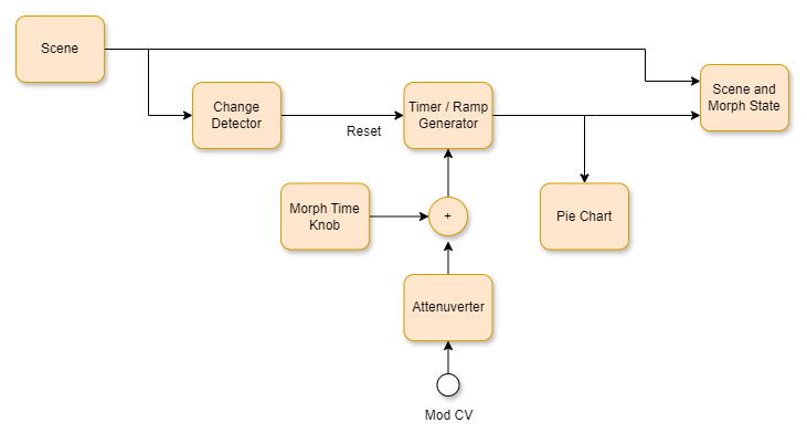
In DISCRETE mode scenes are distinct and independent snap-shots of control settings that can be accessed in any order. You can morph between any two scenes. The MORPH TIME knob controls the amount of time it takes to morph from one scene to another. At minimum setting scenes change instantly. At maximum setting a morph takes 25 seconds to complete. External CV modulation can be used to control morph time too.
In CONTINUOUS mode scenes are treated as an ordered collection that is accessed by a continuously variable control voltage. Certain specific voltages exactly match particular scenes while intermediate voltages produce a blend between neighboring scenes. In the simple case when no CV modulation is applied the OFFSET slider lets you manually sweep through a spectrum of scenes. The RANGE slider switch controls how many different scenes can be accessed.
SEQUENCED mode is similar to CONTINUOUS mode but scenes are accessed in a looping sequence. As the sequencer runs we repeatedly and smoothly morph from one scene to the next over time. The scenes are arranged in a circular fashion so that scene 1 smoothly follows on from scene 16.
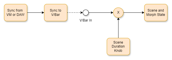
In SEQUENCED mode when nothing is connected to the V/BAR IN socket the timing is synced to your DAW’s tempo or Voltage Modular’s internal tempo when in standalone mode. The SCENE DURATION knob allows you to specify a timing ratio. So for instance the default 1/4 setting means that scene transitions last for the duration of a quarter note. In this situation because the sequence consists of 16 scenes the sequence repeats every four bars.
One important aspect of SEQUENCED mode is that you can use the mouse to adjust Custom Panel controls on the fly and such motion is recorded and played back when the sequence repeats.
Scene Selector
On the left-hand side of the module there is a 4 x 4 grid of buttons called the Scene Selector.
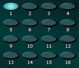
In DISCRETE mode the Scene Selector selects which scene to morph to next.
In CONTINUOUS mode the Scene Selector determines which scene corresponds to a zero volts input (or the OFFSET slider’s minimum setting if no CV modulation is applied).
In SEQUENCED mode the Scene Selector has no effect unless the MANUAL OVERRIDE button is engaged.
To the left of the Scene Selector there’s a CV input socket labelled SCENE. This allows you to use a 0 V to 5 V control voltage to select a scene.

The Custom Scene Trigger module generates a CV suitable for this input making it easy to use standard trigger, gate or clock signals to select a scene.
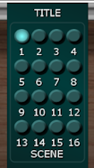
A minature version of the Scene Selector can also be added to a Custom Panel module using its right-click Add scene selector menu option.
You can also add SCENE buttons (that switch to specific scenes) to Custom Panels using the Custom Panel right-click Add special button menu option.
One useful trick when using these special SCENE buttons is to select Learn from MIDI in their right-click menu and associate them with particular MIDI events. This enables you to change scenes by pressing physical buttons on a MIDI control surface or by playing certain notes on a MIDI keyboard.
Note that a Custom IO module must be present in a patch for MIDI events to be received.
When using the Learn from MIDI mechanism to control buttons in Adroit Custom with your MIDI keyboard you might want to reserve say the bottom octave of your keyboard for this purpose and use the Cherry Audio Splitter module to filter out this octave from the rest of your patch.
Manual Override
Beneath the Scene Selector there’s a MANUAL OVERRIDE button.

The MANUAL OVERRIDE button works no matter which operation mode is selected. When engaged it bypasses any effects of CV, sequencing or other controls and forces the scene selected by the Scene Selector to be active. This can be very useful when editing a scene. Because this button has such a major impact on the behaviour of the system it flashes while engaged.
A MANUAL OVERRIDE button can be added to a Custom Panel module via its right-click Add special button menu option.
The Circle of LEDs
On the right-hand side of the module there’s a circle of LEDs that should help you visualize what’s happening.
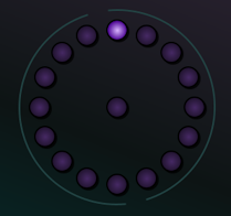
Each LED in the circle represents a scene and during morphing the brightness of each LED shows how much that scene contributes to the final result.
Gate Outputs
Beneath the Circle of LEDs there are 16 output sockets.
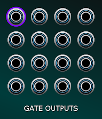
The layout matches the pattern of the Scene Selector with scene 1 in the top-left corner and scene 16 in the bottom-right corner.
These sockets provide gate signals that can be used for a variety of purposes. The output corresponding to the currently active scene is 5 V while the rest are 0 V. A colored ring around a socket illuminates to show which output is 5 V.
When morphing we can be somewhere between two different scenes. In DISCRETE mode the GATE OUTPUT for the target scene is high. In CONTINUOUS and SEQUENCED mode the scene position is rounded down – for instance if we are somewhere between scene 4 and scene 5 then the GATE OUTPUT for scene 4 will be high.
A Simple Demonstration
Before we get into more detail let’s look at a very simple demonstration patch involving just a single control on a single Custom Panel module to put some of the rather abstract concepts discussed above into a practical context.
This patch also introduces the view inside control above scope mode. This extremely useful feature lets you peek inside a Custom Panel module to see exactly what a particular control’s scene data looks like.
Click on the button below to download a .voltagepreset file. Then open the file.
More information on downloading presets
After a few seconds Voltage Modular should launch automatically with the patch shown below…
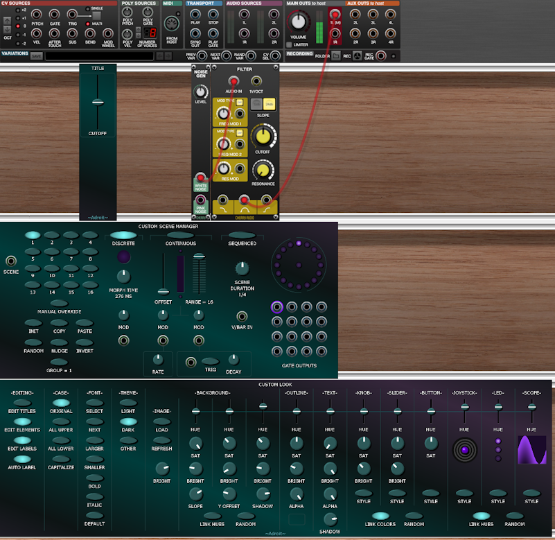
You should also be able to hear some filtered noise playing.
At the bottom of the patch we have a Custom Look module in default state. As discussed in that module’s documentation it is recommended that you always have a Custom Look module at the very bottom of an Adroit Custom patch to ensure that the graphical appearance is stable. We can just ignore the module here.
So, zooming in on the important bits…
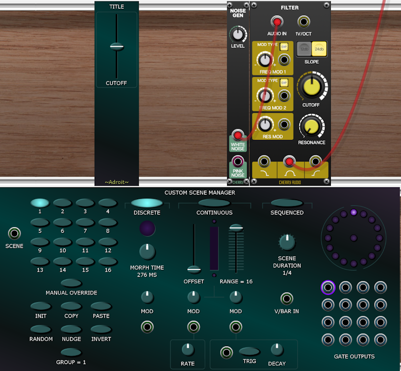
There’s nothing fancy going on here. The sound is produced by passing white noise through the stock Filter module and using the filter’s band-pass output to add color to the noise. A slider has been added to the Custom Panel module and the slider has been mapped to the filter’s cutoff knob. So if you adjust the slider the knob on the filter moves too and we hear the noise frequency characteristics change.
The Custom Scene Manager is in DISCRETE mode and scene 1 is selected so the behaviour is virtually the same as if the Custom Scene Manager wasn’t present.
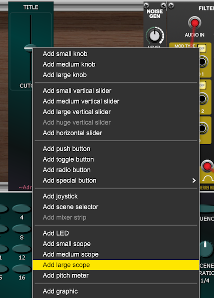
Now, right-click in the large blank area below the slider on the Custom Panel module and select Add large scope from the menu.
Then right-click on the newly added scope and change the scope’s type to View inside control above.
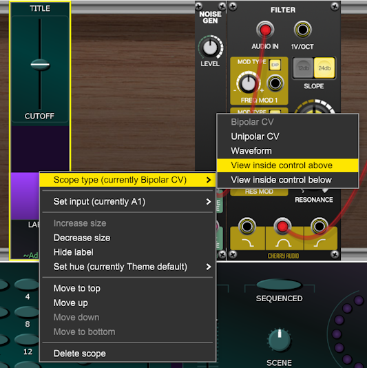
Now when you adjust the slider you’ll see a horizontal white line on the scope move in tandem with the slider. If you look very carefully you’ll also notice that on the left-hand side of the scope a small sliver of the magenta trace changes too. This sliver is small because it shows just what’s changing in scene 1 for the slider control, therefore 15/16ths of the scope’s display doesn’t change.

So far so boring but things are about to get more interesting. First check that Voltage Modular’s tempo is set to 120 BPM (because tempo isn’t saved in a preset)…

Now click on the SEQUENCED mode button (at the top of the Custom Scene Manger module).
You’ll then see the circle of LED’s slowly animating clockwise and a white vertical line on the scope moving from left to right. One cycle takes exactly 8 seconds to complete as the SCENE DURATION knob is set at a 1/4 and 16 quarter notes span 4 bars (or 8 seconds at a tempo of 120 BPM).
Here’s the fun bit – use the mouse to slowly move the slider on the Custom Panel module up and down. Then as well as hearing the color of the noise change, you’ll see that the scope instantly changes to show how the slider’s underlying scene data is affected…

Do this for a while then release the mouse button. You’ll then find that the motion of the slider has been recorded and is then continuously played back in an 8 second (4 bar) loop.
At any time you can click on the slider again and smoothly change the recorded data. Congratulations, you have just learned how to perform a “grab on a motorized control”.
You can grab a motorized control in any mode but it’s particularly useful in SEQUENCED mode.
One caveat is that the motion recording has limited resolution. This is because there are only 16 scenes. So although you can adjust the slider live at high speed, the automation playback will smooth out the changes depending on the tempo and the setting of the SCENE DURATION knob.
However, even though the underlying data is being temporally quantized into just 16 steps, the motion playback uses cubic spline interpolation by default so the results are very smooth and the perceived resolution seems much higher than 16 steps. You can see this effect by turning the SCENE DURATION knob clockwise to slow down the playback speed. Even at very slow speeds the result is silky smooth motion as the cublic spline maths works its magic.
Before moving on from this simple patch let’s take a quick look at DISCRETE mode as this helps illustrate that the scene data behind every Custom Panel control is indeed based on just 16 values.
Click on the Custom Scene Manager’s DISCRETE mode button.
You’ll then see and hear that the sequenced playback stops as we return to a static scene 1. The scope’s appearance changes too…
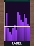
In DISCRETE mode we still get morphing/interpolation between values but it’s not limited to morphing between neighboring scenes so the scope (being just two dimensional) simply shows the 16 discrete values – one value for each scene.
Now try clicking on various buttons on the 4 x 4 Scene Selector. You’ll see that the scope’s vertical white line instantly moves from one scene to another but the horizontal line moves at a pace determined by the MORPH TIME knob and the distance to travel between any two scene settings. Turn the MORPH TIME knob up to about 1.5 seconds and you’ll see the effect more clearly.
We can automate random scene changes in DISCRETE mode by patching an LFO to the SCENE CV input socket…

Two things to note here. The LFO’s polarity switch is set so that it produces a unipolar 0 V to 5 V signal and the LFO frequency is adjusted so that the LFO’s random output changes at a slow enough rate that the morphs complete. This introduces the interesting question of what happens if the scene changes before a morph completes? The answer is an “interrupted morph”. We will cover the creative potential of this later.
The Oram Demo
The very basic patch we’ve just explored has hopefully given you some important insights but it doesn’t really demonstrate the power of Scene Morphing, so let’s take a quick look at using exactly the same principles but scaled up to control ten parameters instead of just one.
This demo patch is named after Daphne Oram a pioneer in electronic music. Her Oramics system has had some influence on the design of Adroit Custom.
Click on the button below to download the patch as a .voltagepreset file. Then open the file.
The youtube video above features the Ink Free font but this isn’t standard on a Mac so it’s been replaced by the default Verdana font in the downloaded patch. If you like the Ink Free font it’s easy to download and install on a Mac. Then you can select it using Custom Look.
Note that there is no need to include a scope beneath a motorized control. They are just very useful as a visual aid when first exploring scene morphing.
To reset all the scene morphing data click on the Custom Scene Manager’s INIT button while holding down the SHIFT key.
There are some useful options in the right-click menu of individual Custom Panel controls too.

Scene Operation Buttons
In the bottom-left corner of the Custom Scene Manager module there are several buttons that perform useful operations on the currently active scene.
When morphing, which scene is active can be ambiguous, but you can always see which is the currently active scene by looking for the highlighted ring around the gate outputs in the bottom-right corner of the module.
Note that in many situations which scene is active can change automatically so it is sometimes best to engage MANUAL OVERRIDE to make sure you know exactly which scene you are operating on.

I could have disabled the Scene Operation buttons when MANUAL OVERRIDE wasn’t engaged but decided that the added flexibility of being able to do “live” operations was worth the risk of one occasionally messing things up.
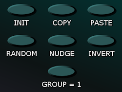
INIT resets all controls in your custom interface that match the GROUP setting (discussed below) to their default state.
COPY copies the active scene’s settings to an internal clipboard.
PASTE copies the internal clipboard to the active scene (providing that a previous COPY operation has occurred).
COPY and PASTE allow scene data to be copied from one scene to another (or let you save a scene and restore it later). As with the other Scene Operations, the clipboard is filtered by the GROUP setting. So it’s possible to copy and paste subsets of a scene.
RANDOM randomizes all controls in your custom interface that match the GROUP setting.
NUDGE is a gentler form of randomization that takes into account current settings. It moves all controls in your custom interface that match the GROUP setting by a small amount.
INVERT inverts the settings of all controls in your custom interface that match the GROUP setting.. If a target is a knob or slider its setting will be adjusted to be a mirror about its central value (for instance a knob set at 9 o’clock will flip to 3 o’clock). If a target is a toggle button it will switch to its opposite state.
Some of these operations can be made available directly in your custom interface by selecting Add special button in Custom Panel’s menu system.
The GROUP button pops-up a menu that lets you choose which group is affected by the INIT, COPY, PASTE, RANDOM, NUDGE and INVERT buttons

By default all Custom Panel controls are in group 1. But sometimes one might want to be do something like only randomize envelope or LFO controls. This can be achieved by changing the group setting of envelope or LFO controls using their Custom Panel right-click menu.
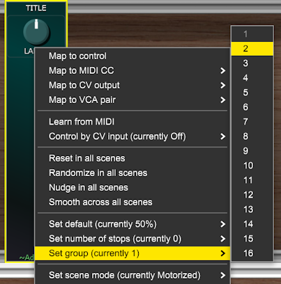
Let’s say we’ve changed all the envelope controls in our custom interface to group 2. Now if we click on Custom Scene Manager’s RANDOM button it will only randomize the envelope controls if Custom Scene Manager’s GROUP is set to 2, 1-8 or All.
If you hold down your keyboard’s SHIFT key and click on the INIT, RANDOM, NUDGE or INVERT buttons then the operation is applied to all 16 scenes rather than just the currently active one. This is the case even if the MANUAL OVERRIDE button is engaged.
Note that the GROUP filtering mechanism still applies when shifted operations are used. If you want to do something drastic like re-initialize or randomize your entire custom interface in every scene regardless of group settings then set GROUP to All before doing the operation.
Discrete Mode
The DISCRETE button switches Custom Scene Manager to DISCRETE mode.

In DISCRETE mode we can switch scenes by clicking on the built-in Scene Selector, by changing a control voltage fed into the SCENE CV input socket, by clicking on a minature Scene Selector added to a Custom Panel or by clicking on a special Scene button added to a Custom Panel.
Special Scene buttons can be useful because you can place them anywhere in your custom interface and label them with any text you like. Also if you right-click on a Scene button you can select MIDI Learn and assign a MIDI event to it. You could then for instance select scenes by pressing particular keys on your MIDI keyboard or physical buttons on a MIDI controller. The same technique can be used to change scenes by sending MIDI from a DAW.
The MORPH TIME knob controls the amount of time it takes to morph from one scene to another. At minimum setting the transition is instant. When the knob is fully CW the transition takes 25 seconds.
You could think of scenes as being rather like individual preset memories. So when you change scene all of the motorized Custom Panel controls (such as knobs and sliders) will change to whatever positions they had when that scene was last selected.
No matter how far controls have to travel to get from their position in one scene to their position in another they will all arrive at the same time. So different controls will often move at different speeds.
An animated pie chart graphic above the MORPH TIME knob shows the progress of a morph.

The image above shows a morph about 1/3 complete.
The base timing set by the MORPH TIME knob can be adjusted by feeding CV to the socket below the MOD label. The knob above the MOD label is an attenuverter for this modulation. The CV law is exponential with a one volt difference causing a doubling or halving of the morph time when the attenuverter is fully CW or CCW.
So if you want very slow morphs set MORPH TIME fully CW, feed 5 V to the MOD input socket and set the attenuverter fully CW. This results in a morph that lasts for 800 seconds.
If you are into really glacial change then just use a higher voltage as no clamping is applied. 10 V for instance should result in a morph that takes over seven hours and 20 V should, I think, result in a morph that lasts for nearly 10 months, though I’ve not tested this!
In order to make morphing from one scene to another as smooth and natural as possible the motion starts gradually, accelerates up to top speed then decelerates as the destination is approached. This is called sigmoid interpolation but if required you can switch to linear interpolation using the Set interpolation option in a Custom Panel control’s right-click menu.
Technically sigmoid interpolation uses linear interpolation too but the interpolation parameter is processed by an S-shaped function in order to add acceleration and deceleration characteristics.
Pure linear interpolation produces a more robotic effect that you might sometimes prefer (although depending on the morph time and what you are controlling the difference might be so subtle as to be unnoticeable). There is also a Stepped interpolation option. This makes the control jump abruptly from one value to another. This can sometimes be useful (for instance to force a change in oscillator tuning to jump rather than slide when morphing) but most of the time the default Normal interpolation option will be what you want.
The circle of LEDs shows the morphing in action.

The LED for the old scene fades out as the LED for the newly selected scene fades in.
When the MORPH TIME is set to a reasonably short period you’ll see this pattern all the time, however with morphing periods longer than a few seconds you might begin to generate interrupted morphs. This is when you change scene before the current morph has completed. Interrupted morphs are not a problem, in fact they can produce very interesting effects as they result in smooth transitions though areas of parameter space that you wouldn’t otherwise encounter.
When a scene change occurs while a morph is still in progress then a new morphing period begins and the currently interpolated settings are used as the starting point to plot a new interpolation to the new destination. This is shown on the circle of LEDs by the center LED lighting up to replace the LED of the previously selected scene. It’s in the center because the starting position of the new morph isn’t a scene, it’s wherever was reached part-way through the previous morph between the old scene (the one selected two steps previously) and the previously selected scene.
An interrupted morph can itself be interrupted by selecting yet another scene before it has completed, so we can go on a journey where we never actually land on a scene but instead explore the space between them.
Continuous Mode
The CONTINUOUS button switches Custom Scene Manager to CONTINUOUS mode.
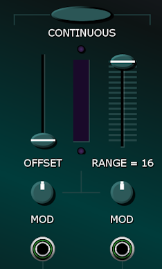
Beneath the CONTINUOUS Mode section there are a couple of utility sub-modules that are normalled to the MOD CV input sockets. Patching cables into the MOD sockets bypasses these.

On the left there’s a sinewave LFO and on the right a Ramp Generator that can be triggered either by by clicking on the TRIG button or by sending a trigger signal to its socket. Although these are very simple modulation sources they are handy when first exploring how CONTINUOUS mode works.
In CONTINUOUS mode scenes have an order and we can only morph between direct neighbors – so between scene 1 and scene 2 or scene 2 and scene 3 etc. Scenes are arranged in a circular fashion so we can “complete the circle” and morph between scene 16 and scene 1.
Unlike in DISCRETE mode, morphing isn’t a transition that occurs in a certain amount of time. Instead a control voltage determines our position in the circle of scenes.
Because scene position is voltage controlled and the voltage can go up or down there isn’t any intrinsic sense of direction in CONTINUOUS mode.
Cubic spline interpolation is used by default so that the morphing is nice and smooth but you can select linear or stepped options instead on a control by control basis using the Set interpolation option in a Custom Panel control’s right-click menu.
Let’s look at the situation where CONTINUOUS mode is selected, scene 1 is selected using the Scene Selector, the OFFSET slider is at its minimum setting, the RANGE slider switch is set at maximum and both of the MOD knobs in the CONTINUOUS section are set at their default 12 o’clock (off) position. This results in scene 1 being active.
Now if we drag the OFFSET slider up and down we see on the Circle of LEDs that we are morphing through the entire continuum of scenes from scene 1 to scene 16 and back to scene 1 again. The motion is visible on the narrow scope between the OFFSET and RANGE controls too.
Next drag the RANGE slider switch down to its minimum setting and once again play with the OFFSET slider. You’ll notice that the Circle of LEDs shows that the morphing is now restricted to the zone between scene 1 and scene 2. However the scope is still looking at the OFFSET before the range scaling is applied. So the RANGE slide switch effectively multiplies what’s shown on the scope by its setting.
Set the RANGE slide switch to 8 and play with the OFFSET slider again and the range shown on the Circle of LEDs will now be from scene 1 to scene 9.

If you are eagle-eyed you may notice that although the 9th LED in the circle of LEDs is illuminated the 9th GATE OUTPUT socket isn’t lit up. Instead the 8th GATE OUTPUT socket is high. That’s because technically the offset value (as shown on the scope) is limited so that it’s always greater than or equal to zero and less than one. In mathematical terms its limits are the half-open interval [0, 1).
So when the OFFSET slider is at maximum we end up with a scene position that’s a tiny bit short of the Scene Selector scene number + the RANGE setting. In other words we are like 99.9999% of the way to scene 9 but as the GATE OUTPUTS round down to the nearest scene they say we are still in scene 8 rather than scene 9.
Generally speaking this is just nerdy detail that you don’t need to worry about!
Let’s look at modulating the scene position. Adjust the OFFSET slider to minimum and the RANGE slider switch to maximum again. Then introduce some modulation by turning the MOD knob beneath the OFFSET slider fully CW.
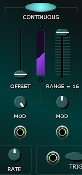
You’ll then see the scope showing a portion of a sinewave and the Circle of LEDs will show a pendulum like motion as the scene morphs around the circle and then back again. Turn the RATE knob up slightly if you like.
Now reduce the RANGE and you’ll see that instead of going all the way around the circle, the motion is limited to however many scenes the RANGE slide switch is set to.
Now with RANGE set roughly in the middle, slowly turn up the OFFSET slider. You’ll see that the start position shown on the Circle of LEDs increases. But because the LFO modulation is turned fully up the signal shown by the scope goes off the top of the scope and the little LED above the scope illuminates to indicate modulation clipping. This limiting action is deliberate and has creative use. Looking at the Circle of LEDs you’ll see that the pendulum motion stalls for a while.
But let’s say you don’t want this modulation clipping action. Then instead of using the OFFSET slider we can change the scene origin using the Scene Selector.
To illustrate this, set OFFSET to minimum and RANGE to maximum. If the Scene Selector is still set to scene 1 and the LFO MOD is still fully CW then we should return to the full pendulum motion we had before. Now select scene 5 on the Scene Selector. Notice that now instead of the pendulum swinging from scene 1 around the circle back to scene 1, it swings from scene 5. The range is still the full circle though, with the pendulum swinging through the scene 16 to scene 1 boundary.
This will probably all seem rather confusing at first but you should soon get the hang of it with the help of the scope and the Circle of LEDs. The Continuous Mode Function diagram in the technical appendix at the bottom of this page might be useful too.
The idea is that by combining the Scene Selector, OFFSET slider and RANGE slide switch settings with modulation, one can arrive at many kinds of sweeps through the continuum of scenes.
One very useful type of scene position modulation uses an envelope generator. The built-in ramp generator is just a very primitive envelope generator with an instant attack and a decay controlled by the DECAY knob.
Set the Scene Selector to scene 1, OFFSET to minimum, RANGE to maximum, double-click on the MOD knob underneath the OFFSET slider to set the knob to 12 o’clock (to turn off the LFO modulation) and then turn the MOD knob beneath the RANGE slider fully CW.
One thing to be aware of is that the MOD knobs aren’t controlling OFFSET or RANGE. They just happen to be below these controls. If you look carefully there’s an upside down T graphic that is there to try and remind you that the two sources of modulation feeds into the position signal shown by the scope.
The schematic diagram at the bottom of this page might help make it clearer that in CONTINUOUS mode the scene position is determined by adding together the OFFSET slider’s setting and the CVs from the two modulation sources.
So the ramp generator creates a morph that starts at scene 1 and moves all the way around the circle of scenes when triggered. Note that the modulation signal is in effect upside down compared with a regular envelope generator. This makes sense but might not at first sight.
OK, so if you now click on the TRIG button you’ll see a ramp on the scope and the Circle of LEDs will show a complete sweep from scene 1 through to scene 16 , finally completing the circle back at scene 1.

The image above looks very similar to the earlier one but notice that the MOD knob settings are different.
This situation is slightly over the top as you will rarely want to morph through 16 different scenes inside the span of a single envelope cycle. To accomplish very simple morphing where say scene 1 is used for the start of a sound and scene 2 represents the end of the sound just set RANGE to 1.
When morphing between scenes inside the duration of a note you generally wouldn’t want the settings of any envelope generators to morph at the same time. This can be achieved by switching any such envelope controls in your interface to Shared rather than Motorized Scene Mode (something we will cover elsewhere).
Sometimes you might want to change the scene mode of all controls on a Custom Panel and it can be a bit tiresome having to do this control by control, so there’s a shortcut in the All elements sub-menu of Custom Panel’s main right-click menu.
Sequenced Mode
The SEQUENCED button switches Custom Scene Manager to SEQUENCED mode.
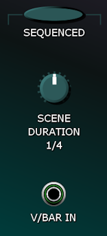
SEQUENCED mode is similar to CONTINUOUS mode but is designed for situations where we want to morph through all 16 scenes in a tempo-synced loop. Cubic spline interpolation is used by default so that Custom Panel controls change smoothly and scene 1 is considered the natural successor to scene 16 so there is no discontinuity in the morphing as we complete the circle and begin again.
If nothing is connected to the V/BAR IN socket then Custom Scene Manager syncs to your DAW’s tempo if Voltage Modular is being run as a plugin or Voltage Modular’s internal tempo clock in standalone mode. This is useful because at least the tempos match, but without using V/Bar the sync is free-running so you can’t ensure that Custom Scene Manager’s internal sequencing starts at exactly the same time as any external sequencing.
To gain full control over SEQUENCED mode simply add a Custom Transport module to the patch and connect its V/BAR OUT socket to Custom Scene Manager’s V/BAR IN socket.
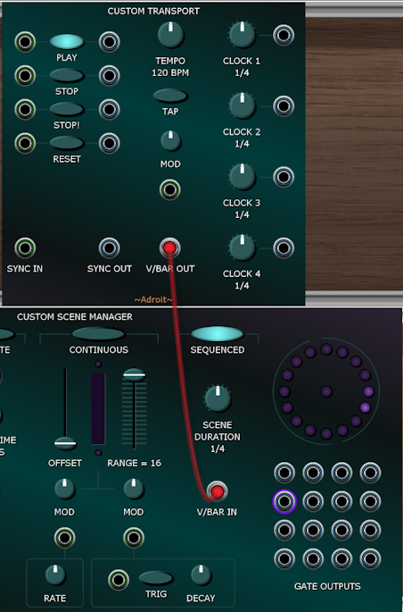
The Custom Transport module can also be used independently of Custom Scene Manager as one might want to have transport control over other aspects of a patch without ever using SEQUENCED mode (or even scene management in general). So off-loading transport control to a separate module not only simplifies Custom Scene Manager, it gives us extra flexibility too.
V/Bar stands for Volt Per Bar and was developed as a key technology in LSSP. Click here for an introduction to V/Bar.
Scene Modes
A very important parameter of every Custom Panel control is its scene mode. The default is motorized but you can change any control’s scene mode via its right-click menu.
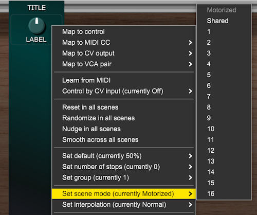
A control with a motorized scene mode changes setting when the scene changes. Imagine that there is a little servo-motor behind the panel that physically changes the control when a scene change occurs. This might be an immediate jump to a new setting or a slow morph depending on the Custom Scene Manager settings that we’ve already discussed
You can override a motorized control by “grabbing” it with the mouse (or via MIDI CC if the Learn from MIDI option has been used).
A control with a shared scene mode has the same setting in all scenes. In other words its setting is shared by all scenes. This allows some controls to be completely unaffected by scene morphing.
The numbered scene modes allow you to have controls that only become active when a particular scene is active. This allows you to have multiple controls all mapped to the same target that take turns in controlling the target depending on which scene is active.
One application in Custom Scene Manager’s SEQUENCED mode would be to build a 16-step sequencer using 16 sliders with scene modes from 1 to 16 all mapped to the same target (whether that’s a control on another Voltage Modular module, a Custom IO CV output or a Custom IO MIDI output). This is demonstrated in the ZeroSeq demo patch below.
Another application in Custom Scene Manager’s DISCRETE or CONTINUOUS mode might be having one bank of controls for scene 1 and a mirrored bank of controls for scene 2.
In certain situations you may want to change the scene mode of lots of controls at once so there’s an All elements shortcut that enables you to change the scene mode of all of a Custom Panel’s controls…

Note that this option in a Custom Panel’s right-click menu only appears when a Custom Scene Manager is present in a patch.
The Angels Demo
The Angels patch demonstrates using Custom Scene Manager’s DISCRETE mode to morph between ten different vowel sounds. It was inspired by this vocal formant choir patch posted by Grant Middleton on Cherry Audio’s forum.
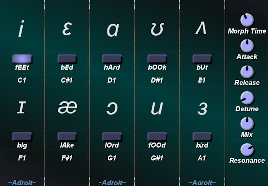
Click on the button below to download the patch as a .voltagepreset file. Then open the file.
You can select the vowel by clicking on the buttons with a mouse but it’s much more fun to “play” the vowels by pressing MIDI keys C1 through A1. Keys above A1 control which notes to play.
The results aren’t super realistic but it’s polyphonic and can produce some very nice synthetic cathedral style choir sounds. If you want to get really dramatic turn up the Morph Time, Detune and Resonance knobs and change vowels while playing dissonant chords. You should then be able to produce something similar to the epic György Ligeti sounds featured in 2001 : A Space Odyssey. Try the pitch bend and mod wheels too.
You can remap the buttons by right-clicking on them, selecting Relearn MIDI and pressing a MIDI key of your choice. You can also double-click on the text labels to change them to remind yourself which keys map to which vowels.
As the Arturia KeyStep is such a popular device there’s a version of the demo that’s mapped to its small keyboard.
In this version vowel selection is done via the keys F2 through D3.
Note that the knobs in these two patches are set to shared scene mode. So a change in scene (vowel selection) does not have any impact on them.
The ZeroSeq Demo
The ZeroSeq patch demonstrates combining Custom Scene Manger’s SEQUENCED mode with Custom Panel controls that are configured to use different numbered scene modes. The result is a 16-step sequencer with individual channels for pitch, volume, filter cutoff and filter resonance. It is called ZeroSeq because no sequencer module is used to achieve this.

Click on the button below to download the patch as a .voltagepreset file. Then open the file.
The color-coded RESET and NUDGE buttons on the left of the interface enable you to change 16 controls with a single mouse click.
Individually mapping the controls for all 16 steps would be extremely tedious and difficult to do by hand, but in practice all one needs to do is map the controls for step 1 and then use Adroit Custom’s intelligent cloning feature to automatically map the other 15 steps using a relatively small number of mouse clicks and key presses.
The Duality demo
The Duality Morphing Synthesizer patch demonstrates using Custom Scene Manager’s CONTINUOUS mode to morph between two different scenes. It has its own webpage here.

Inside the Custom Scene Manager
This technical appendix presents a few schematic style diagrams that might help some people better visualize how Custom Scene Manager works.
