Table of Contents
Introduction
These demo patches use the Adroit Custom bundle along with modules from Cherry Audio’s Core + Electro Drums bundle.
For an overview check out the Adroit Custom page.
If you are only interested in quickly trying out presets then scan through this page looking for the black Download buttons. For help on running Voltage Modular presets see information on downloading presets.
For reference style information read the pages on the individual modules – Custom Panel, Custom Look, Custom IO, Custom Transport, Custom Scene Manager and Custom Scene Trigger.
Note that in most of these presets the EDIT LABELS and EDIT ELEMENTS buttons on the Custom Look module are engaged.
This means that you can modify anything you like but if you want to use these demos in a more practical sense then you might want to disengaged these buttons.
In particular, if you disengage the EDIT LABELS button then you’ll no longer see the label editor annoyingly pop up when you happen to click on a label.
Simple Mixer
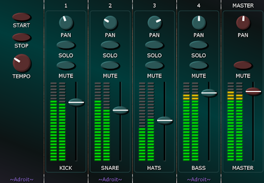
This preset demonstrates a four-channel mixer. It’s rather basic but it illustrates the first steps involved in constructing modular mixers in Adroit Custom. You can use additional modules to add more channels and things like EQ, effect sends and groups but it’s essential to understand how this simple mixer works first before adding such extra functionality.
The complete patch is shown below.
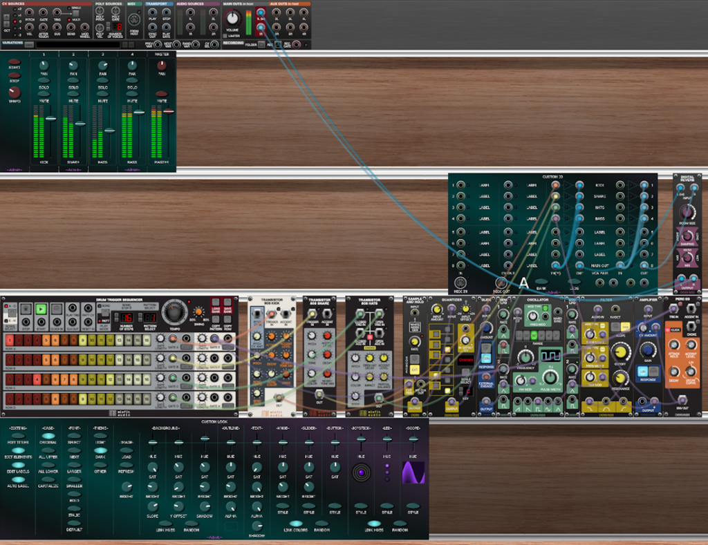
The top cabinet contains the six Custom Panel modules used to create the interface. The second cabinet contains a Custom IO module and a stock reverb module. The third cabinet contains a little drum machine and a generative bass voice just so that we have some sound sources to play with. The bottom cabinet contains a Custom Look module.
The main components we are interested in are the five Custom Panel modules that have faders and LED meters and the Custom IO module as it is these that form the mixer.
The Custom Panel modules with faders etc are pretty simple as each has just one element – a mixer strip. Mixer strip elements save you having to build everything out of individual sliders, buttons and so on, plus there is only one thing to map per channel – that is which VCA pair it uses.
The mixer strips for the kick, snare, high-hats and bass channels have their mixer VCA pairs set to A1, A2, A3 and A4 respectively.
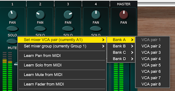
So the Custom IO VCA pairs 1 through 4 are controlled by the four input channel mixer strips. The user-editable labels have been changed to reflect which VCA pair does what…
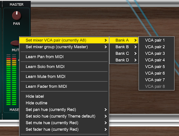
The mixer strip on the Custom Panel for the Master channel needs a bit more configuration than the others. Its VCA pair is set to A8 (we could have used A5, but it’s nice to have a bit of space on the Custom IO module). Its mixer group is set to Master. This is required because we don’t need or want a SOLO button on the master strip. Finally the hue of the various controls has been changed so that they use red instead of the theme default.
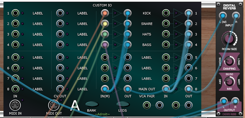
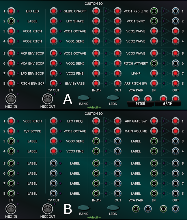
Returning to the wiring on the Custom IO module…
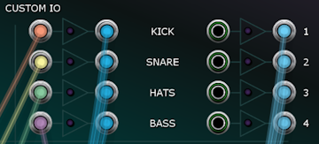
In the image above the sockets on the left are the inputs of the left-hand VCA of each of the four VCA pairs A1 through A4. These are connected to the four audio sources in the cabinet below. Note that the inputs for the right-hand VCA of these pairs are not connected to anything. This is because they are normalled to the left input of the pair. The labelling IN(M) at the bottom of the left column of inputs is a reminder of this. The M stands for Mono.
Now as the mixer strips and VCA pairs look after all the details of volume control, muting, soloing, panning and metering all we have left to do is sum the outputs of the first four VCA pairs to the inputs of the VCA pair used by the Master channel. This is what the cyan-colored cables are for.
So the left outputs from VCA pair A1 through A4 are connected to the left input of A8 and the right outputs from VCA pair A1 through A4 are connected to the right input of A8. Finally the main stereo output of the mixer is taken from the outputs of VCA pair A8 and sent to the reverb module for final processing.
We might return to mixing at a later time to look at adding things like sends, returns and groups. Although this mostly involves extending the principles already discussed so you may have already figured it out.
Vocoder
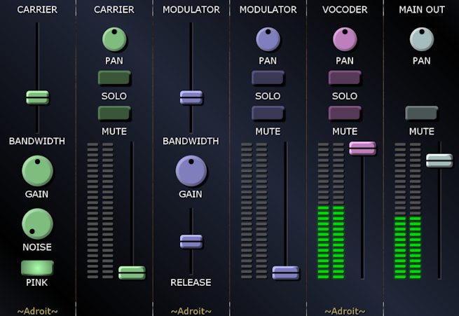
This preset demonstrates a 10-channel vocoder. A vocoder takes a modulator signal (typically a human voice) and imposes it’s frequency spectrum onto a carrier signal (typically a fairly bright synthesizer sound).
In this patch the modulator comes from Voltage Modular’s AUDIO SOURCE 1L socket. The carrier is generated by a Poly Octave Oscillator and an optional noise source. You can of course replace this divider organ type oscillator with something more sophisticated but it’s polyphonic, fine for producing the classic vocoder sound and doesn’t use a great deal of CPU.
To hear anything you need to simultaneously feed an audio signal into Voltage Modular and have some MIDI notes playing. If you are using a laptop you could experiment just by talking into your laptop’s microphone while playing something using Voltage Modular’s QWERTY musical keyboard.
You can mix between the carrier, modulator and vocoder signals using the faders. Usually you would have just the vocoder signal as output but it can be handy to listen to the inputs while setting up. And sometimes you may want a little bit of the other signals in the mix too.
The bandwidth sliders have something of a sweetspot at about 30% so the sliders have this set as their default position. But you may find if useful to tweak them depending on the source material.
The complete patch is shown below.
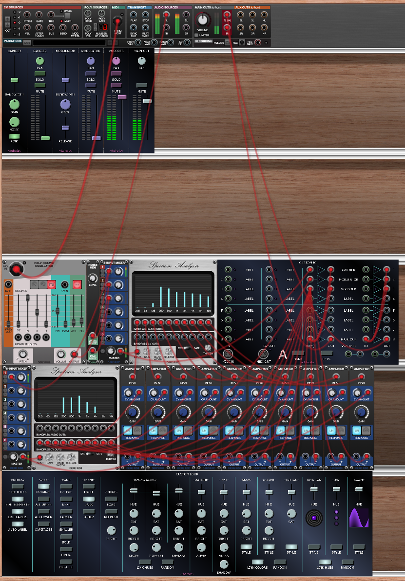
The vocoder uses the Spectrum Analyzer module that’s included in the Core bundle. This module doesn’t seem to get much attention (possibly because Cherry Audio haven’t documented it) but it’s a very useful bank of bandpass filters and envelope followers.
One spectrum analyzer is used to split the modulator signal up into 10 bands an octave apart and convert the amplitude of each band’s signal to a control voltage using the built-in envelope followers.
Another spectrum analyzer splits the carrier signal into 10 bandpass filtered audio signals which are passed to 10 VCAs. The gain of each of these VCAs is controlled by the corresponding envelope signal from the first spectrum analyzer.
The outputs of the VCAs are all summed to one signal but you could be a bit more creative if you want to modify this simple demo. You could pan the signals to diiferent stereo positions for instance.
The VCAs are mapped as you’d expect so that each band in the modulator controls the volume of the matching band in the carrier but you could experiment with rearranging things.
Meta 56 Sequencer
This preset demonstrates a fun sequencer that coordinates multiple instances of Cherry Audio’s Eight-Step Sequencer to produce an 8-step sequencer with seven channels that can simultaneously remotely control knobs, sliders and buttons on Voltage Modular modules, output CV, output MIDI CC and control VCAs . It’s called Meta 56 because 7 times 8 is 56 and it uses a sort of meta programming technique whereby Adroit Custom controls something that controls Adroit Custom in order to control something else. A Custom IO module is part of the “interface” rather than hidden as you need it to access the CV and MIDI outputs and the VCA pairs.
Note that this patch on its own doesn’t do anything useful. You need to add something that requires sequencing.
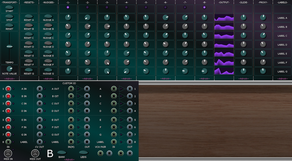
The strange thing about this sequencer is that the outputs are mapped via the knobs in the -PROXY- column. This is the “meta” aspect. The interface controls the settings of the external sequencers and these sequencers control the settings of the proxy knobs and as these knobs are regular Custom Panel knobs they can be mapped to remotely control knobs, sliders and buttons in your patch, output CV, output MIDI CC and control the gain of VCA pairs.
It might take a moment to get your head around the fact that control flows out of Adroit Custom then back in and then back out again, but it all makes sense once you realize that you can leverage the mapping ability of Custom Panel knobs to get easy access to some neat features.
What takes more getting one’s head around is combining this little sequencer with Custom Scene Manager so that by morphing from scene to scene you can morph from sequence to sequence but don’t worry about that now as Custom Scene Manager hasn’t even been released yet.
To get you started the proxy knobs are mapped to the CV OUT sockets on Custom IO Bank B that are labelled A OUT through G OUT. By default these deliver 0 V to 5 V control voltages that you can use to drive any modules you like.
So, if all you need is 0 V to 5 V CV for sequencing then you can ignore the -PROXY- knobs altogether and just use the signals provided by the sockets labelled A OUT through G OUT.
The VCA pairs labelled A through G are also mapped. By default as linear attenuators. You might want to use some of them to control modulation depth perhaps.
You can change any aspect of the mapping by right clicking on the proxy knobs. As each knob can have four independent mappings there are two spare mappings available on top of the default CV and VCA mappings.
The complete patch is shown below.
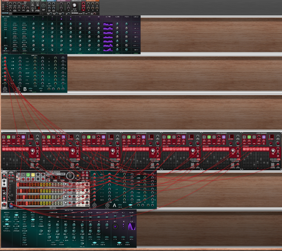
For reference, on its own this sequencer produces a CPU load of about 8 or 9 % on my laptop and it took me about six or seven hours to build. The main task was carefully mapping the 56 main knobs on the interface to the 56 sliders on the 7 8-step sequencers and setting groups so that the reset and nudge buttons only targeted specific rows.
The Drum Trigger Sequencer is used to drive the LEDs on the interface. It’s a bit clunky but this was the easiset way I could think of to implement this feature. The LEDs stay on for the duration of the GATE LENGTH parameters set for the Drum Trigger Sequencer channel outputs. These are set to 250 ms so that the LEDs don’t flicker on and off too much but this also means it’s possible to see either no LEDs illuminated or two or more at once depending on how fast the rate is. This isn’t a malfunction.
Having said that the use of the Drum Trigger Sequencer is a bit clunky, it does actually have the advantage that you can use its 8 GATE outputs as per-step trigger outputs to drive things in your patch.
As already mentioned, the Meta 56 patch doesn’t do anything on its own so here’s a test patch that demonstrates a very simple application using an oscillator and a filter (plus a reverb module just to make it sound a little less sterile).
Remember we are just looking at functionality here not trying to make something that sounds amazing, but a bit of reverb goes a long way. I perhaps wouldn’t go as far as Omri Cohen’s “Reverb is Life” but it’s still pretty essential in electronic music!
The implementation part of the patch is shown below. I class this as an “implementation” because (apart from the red cables) the inner workings of Meta 56 aren’t shown.
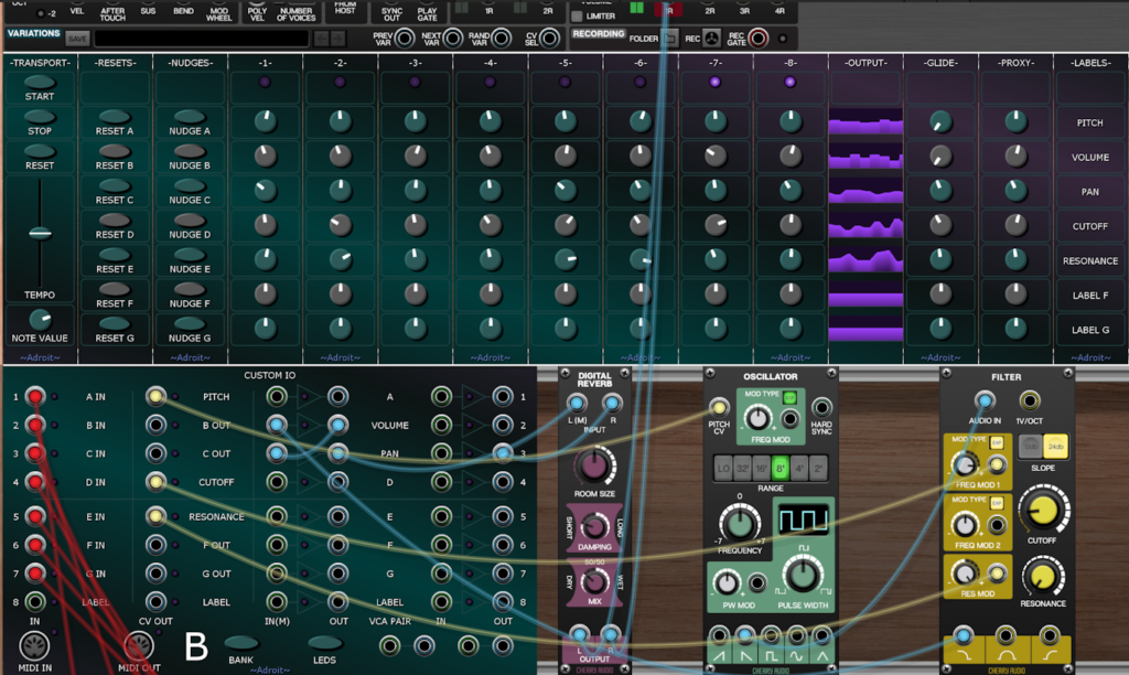
The cyan-colored cables are audio, the pale yellow ones CV.
Channel A of the sequencer controls the oscillator’s pitch. Channel B controls volume. Channel C controls pan. Channel D controls the filter’s cutoff frequency and Channel E controls its resonance. The various user-editable labels have been set to reflect these functions.
Try clicking on Meta 56’s reset and nudge buttons to see what’s going on.
You might notice that the pitch is quantized and covers a small range yet when you look at the 8-step sequencer that’s used to implement Channel A, its output is not quantized and it’s ranging from 0 V to 5 V. Also there is no Quantizer module. How can this be?
Well if you right click on the -PROXY- knob for Channel A you’ll see that the knob is set to have 13 stops. This means it serves as a 13-position rotary switch rather than a continuously variable knob. Why 13 rather than 12? Because the range of the mapping to CV output B1 is set to be 0 V to 1 V and this includes the first note of the octave above. C2 to C3 when C2 = 0 V. So it’s 12 notes of an octave plus the first note of the octave above. If you set it to 12 stops instead the tuning is all wrong.
In case you were wondering why the set number of stops menu includes odd options like 25, 37 and 49 it’s to support two, three and four octave ranges plus one. The same thing applies to bipolar shifting, if you want -12 semitones to + 12 semitones that’s 25 semitone steps not 24 as you need to include the zero. This kind of thing trips up a lot of people, so don’t worry if it seems confusing.
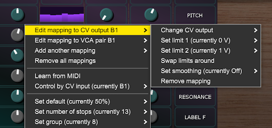
The eagle-eyed amongst you may also notice that the group setting is 8 rather than the default 1. This is because groups 1 through 7 are used by the application to make the reset and nudge buttons target specific rows of the main 56 knobs.
Rather than using CV, we could have mapped the proxy knobs to the filter’s CUTOFF and RESONANCE knobs and saved a couple of cables but using CV means you can tweak the knobs on the filter to fine-tune things.
To make the volume control more natural the VCA type for VCA pair B2 is set to Exponential attenuators rather than the default Linear attenuators.
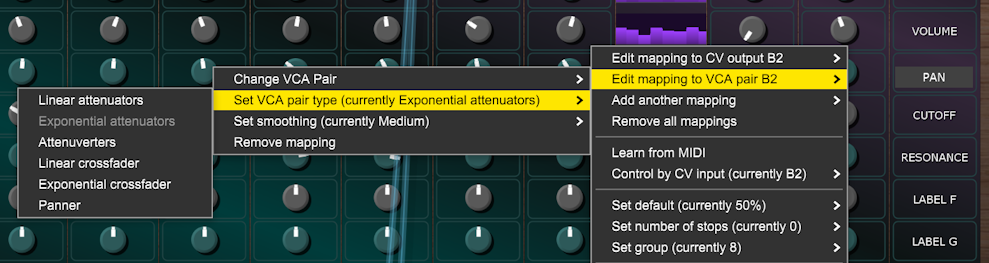
As you have probably guessed the VCA pair type for the B3 VCA pair is set to Panner.
By the way Meta 56’s transport doesn’t sync to a DAW but it shouldn’t be too difficult to rewire things so that it does, providing you’ve done that kind of thing previously.
Mono Synth
This preset demonstrates a three VCO monophonic synthesizer with a tuning setup designed to make it easy to create three note chords, It also provides useful visual feedback on envelope and LFO behaviour.
It’s unlikely that you’ll be building something on this scale while getting to known Adroit Custom but it shows the kind of thing that is possible.
It should also give you a feel for the scale of Adroit Custom project that your computer can handle. This patch results in a CPU load of about 10% on my mid-range laptop, but CPU load isn’t a great indicator of how close we are to buffer underrun.
Custom IO modules use more resources when their LEDs are switched on so always have the LEDS button disengaged if you don’t need the LEDs for troubleshooting.

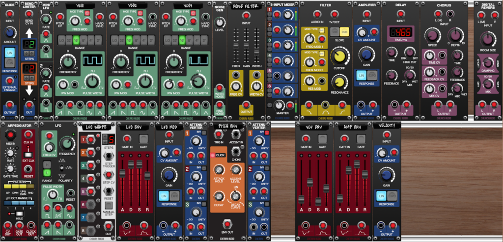
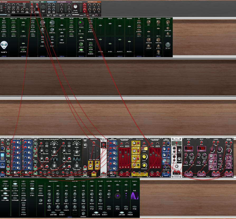
The complete patch is shown below.

The top cabinet contains the Custom Panel modules used to create the interface.
The second cabinet is empty. You’ll often want to add an empty cabinet to separate the interface from the implementation part of a patch as it looks nice and neat when you use zoom and scroll so that only the interface is visible. You’ll also want to hide the cables too. It is actually possible to drag Voltage Modular’s I/O Panel down so that it’s out of the way but unfortunately this change isn’t remembered so it will be back at the top the next time you run Voltage Modular.
The bottom cabinet contains a Custom Look module but the third and fourth cabinets are where most of the work is done. If you are familiar with Voltage Modular then you’ll probably recognize all the modules on the right. In general those in the third cabinet form a fairly standard subtractive synth chain with audio signals moving left to right while those in the cabinet beneath are looking after modulation.
Mostly what makes the full patch image shown earlier look so complicated is all the wiring from the two Custom IO modules on the left. All of the Custom IO connections are labelled so it’s not a complete mess, but it is non-trivial.
It took me about 15 hours to build this patch but I (supposedly) know what I’m doing. Don’t attempt to build something like this until you have a good understanding of how Adroit Custom works. Having said that, this patch was the first large scale thing I built using the initial released version of Adroit Custom and it was a great learning experience. I’d do things differently now but one has to go through a learning process to advance.
If you really do want to pick this patch apart then you might want to add color coding to the cables using whatever scheme you normally use.
But it’s perhaps best just to play with the interface as if it was a ready-built synthesizer and learn how some of the less obvious elements work. It’s not a carefully designed masterpiece (and there are one or two loose ends like oscillator sync not being finished) but it can actually produce some nice noises. Then if you are curious about how a particular feature works then right-click on the relevant controls, check the settings and trace the mapping. Eventually you should be able to modify and extend it. One obvious modification might be to make it polyphonic but that would not be straightforward. It would be easier to build a polyphonic synth from the ground-up. Something we will look at next.
Planet Z Polysynth
This preset demonstrates a two VCO polyphonic synthesizer. It uses Custom Panel’s built-in randomization and grouping facilities to help you discover strange sounds literally at the push of a button.
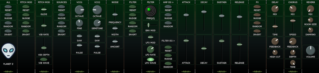
It doesn’t use any Custom IO modules, doesn’t provide any visual feedback, only has two VCOs and has simple modulation so although it’s polyphonic it might actually be a little easier on your computer than the Mono Synth.
The complete patch is shown below. Because it’s a wide interface there are two blank cabinets between the interface and implementation just so that you can zoom out enough to see the entire interface without the implementation becoming visible.
The interface is divided into sections and each section has a number of special buttons that allow you to reset, randomize, nudge or invert the settings of the controls in that section. So for instance the FILTER section has the following column of buttons that affect the filter controls.
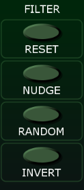
Each of these buttons has its group set to match the group setting of the controls it affects. In this case group 2.
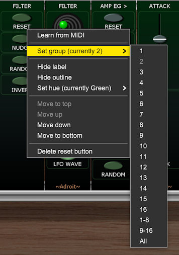
So the filter controls that are affected by these special buttons also have their group set to 2. As shown with the joystick below.
On the far-left we have a column of special buttons that provide global functions for reseting, randomizing etc all of the sections at once.
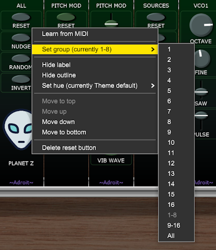
However, we don’t want the VOLUME control in the bottom-right corner of the interface to be affected by these buttons so this has its group set to 16 and we use 1-8 rather than All as the group setting for the buttons. 1-8 means the buttons affect any control that is in group 1 through 8 and the various sections use groups 1 through 6.
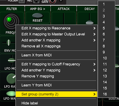
Something you might have noticed in the image above showing the joystick’s menu is that its x axis has two mappings – one to Resonance and another to Master Output Level. The first controls the filter’s resonance and the other the master volume of the Poly 6-Input Mixer.
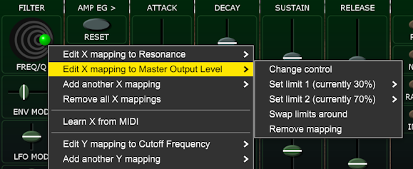
The purpose of the second mapping is to adjust for the reduction in volume as resonance is increased. Limit 1 amd limit 2 are set so that the mixer’s output level varies from 30% when resonance is at minimum up to 70% when the resonance is at maximum. Some modern resonant filters do this compensation internally but not the stock VCF in Voltage Modular but as we can have up to four mappings per control it’s easy to add this feature. You could tweak these numbers to adjust the ratio and also determine how hard the filter can be driven.
Another mapping detail worth mentioning is that behind the OCTAVE knobs. These control the RANGE controls on the Poly Vintage Oscillators.
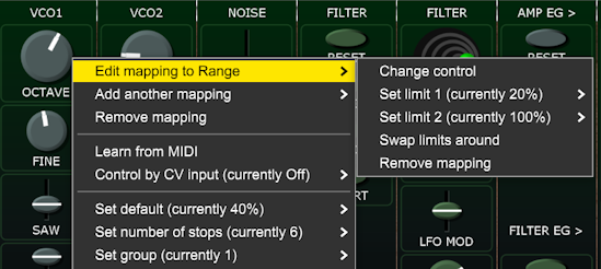
Limit 1 is set to 20% as we don’t want to include the sub-audio LO setting of the oscillator’s RANGE control (10% works too as the RANGE knob rounds the numbers to its nearest stop). The OCTAVE knob’s number of stops is set to 6 as we have six different octaves available from 64′ to 2′.
Stella
This preset demonstrates some ways that you might encapsulate a patch for use in live performance. It produces just a four-bar loop but there are enough options for manipulation that one could jam with it to produce an extended piece. This is easier if you use MIDI Learn and a control surface but you can do a lot with just a mouse or touchpad.

Click on the button below to download the .voltagepreset file.
In the upper cabinet of the interface we have a four-step chord sequencer and a mixer for the five “instruments” – kick, snare, arps, root and stabs. In the lower cabinet there’s a scope for eye-candy and control sections for most of the individual instruments. The arps are hard-wired so don’t have any controls in the lower cabinet but you could add some if you wanted.
The intention here, as with all the demo patches, is to demonstrate techniques that you could use in your own work rather than to be definitive in some way. The beauty of Adroit Custom is of course that you can modify anything you don’t like.
This is a fairly demanding polyphonic patch that uses 98 modules so it might not be possible to get it to run without glitching if you have an old machine. But it should still be possible to adapt most of the ideas to run on slower computers.
Even on a mid-range machine it will probably crackle a bit when you first load it. This should go away once the patch has “warmed up” (which usually takes only a few seconds). If you are online this warm up can take much longer as Voltage Modular has a chat with Cherry Audio’s server. In general it’s best to be offline when doing anything demanding with audio as all kinds of things can be going on in the background, especially if you use cloud-based services.
Here’s a two minute youtube video that might help if you can’t get the preset to run at all.
The implementation part of the patch is shown below.
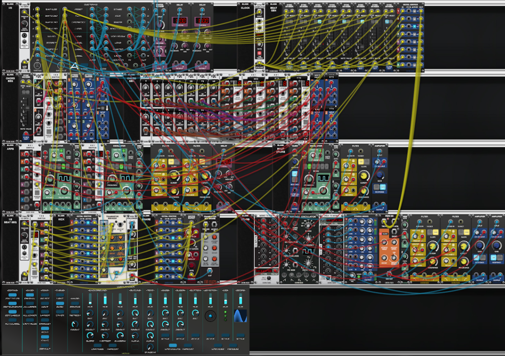
As you can see the implementation isn’t quite as user-friendly as the interface!
The cables are color-coded – yellow is used for logic, red for CV and cyan for audio. Although the chord generator uses a different scheme. I’ve probably messed up a few of the cable colorings but overall the color-coding should still help.
Let’s look at the individual sub-systems broadly working left to right, top to bottom. Each sub-system has a 6HP Blank Panel on the left with a title as this really helps in navigation. One might be extremely familiar with what is what when building something like this but when you come back to it much later such internal documentation can be very useful.
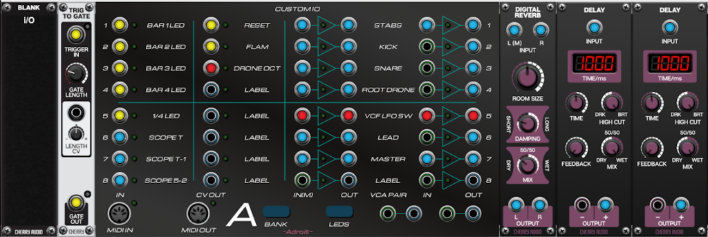
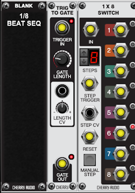
The Trig to Gate module extends a very brief trigger signal for a longer period so that the 1/4 BEAT LED lights up properly.
The Custom IO module handles various input and output tasks for the 20 Custom Panel modules that make up the interface.
The inputs on the left receive the signals that drive the LEDs and the scopes. The wide oscilloscope is merely decorative so if your machine is struggling it would be the first thing to axe. But even though this uses three scopes and two delay lines, removing them isn’t going to make a huge difference as the CPU load is pretty well spread throughout the patch.
The wide-screen scope is included as an illustration of how to extend the time window of scopes using the Delay modules. As the scope time window is one second all you need to do to extend the period viewed is to send each scope a signal that’s delayed by one second relative to the scope on its right. This isn’t of any practical use here but if you wanted to analyse and compare various control signals over longer periods than one second then this is how you could achieve it.
The RESET output is mapped to the RESET button on the interface and is wired to all the RESET inputs of the various clocked modules. You shouldn’t ever need this feature but while developing this patch it was often required as clocked systems are fragile (which is one of the main reasons for V/BAR in LSSP).
The FLAM output is a CV that switches the snare between single and double hits by modulating the number of bursts from the Micro Burst module depending on the setting of the FLAM button on the interface.
The DRONE OCT output sends a CV to the root drone voice to shift its octave depending on the setting of the ROOT OCTAVE 4-position slide switch.
The bulk of the VCA pairs are used to implement the 5-channel mixer. But pair 5 is used as a 1-pole 2-way switch that allows the right-hand filter in the stabs voice to either have an independent LFO driving its cutoff frequency or to use the same LFO as is modulating the left-hand filter depending on whether the STEREO LFO button is engaged.
Some dead simple reverb is slapped on the final output.
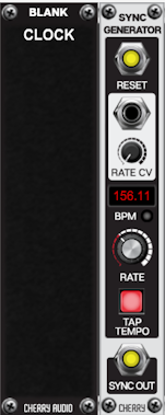
This is the master clock. It pumps a 96 PPQN signal to everything else in the patch. Its RATE and TAP TEMPO controls are targets for the TEMPO and TAP controls on the interface. Sometimes clicking three or four times on the TAP button will produce better results than the more cerebral process of tweaking the TEMPO slider.
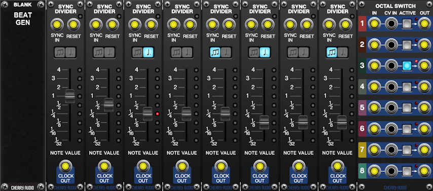
This large array of Sync Dividers is used in place of a single one in order to generate temporal stability. If you switch the division of a single module then everything slides out of sync with the outside world. Using so many modules looks expensive but all they are doing is counting sync pulses so the CPU load is minimal.
The 1/4 and 1/8th divider outputs send signals elsewhere too, but the main purpose of this bank is to offer a wide choice of rhythm pulses to the “Stabs” instrument.
The radio buttons shown above map to the Octal Switch module on the far-right of this sub-system. The outputs of which are all fed to the percussion envelope generator of the Stabs sub-system. In live performance flipping between different divisions can add lots of interest if it’s done right.
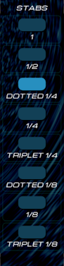
This is where things get a little tricky as I’m deliberately using only the stock modules provided in Core. So rather than using LSSP we are constructing things at quite a low-level. The Chord Sequencer has four steps and is driven by the Sync Divider on the left. We could have used the left-most divider in the Beat Generator sub-system but given the low CPU demands of a Sync Divider it wouldn’t achieve any real increase in efficiency.
The one clock per bar trigger from the Sync Divider’s output shifts the 1 x 8 Switch through a four-step cycle. The input of this switch is a static 5 V from the DC Source module. So in bar one the 1 output of the switch is 5 V and the other outputs are 0 V. In bar two the 2 output of the switch is 5 V and the other outputs are 0 V. And so on.
These outputs pass through four independent attenuvertors. Each of these attenuvertors is a target of one of four large sliders labelled CHORD 1 through CHORD 4 on the interface. These sliders have limits of 0% and 100% and 8 stops so the outputs of the attenuvertors vary from 0 V to 5 V in equal steps. This matches up with the 8 CV settings of the 8 x 1 Switch modules in the Chord Generator sub-system.
All four outputs of the attenuvertors are summed by the MULT module so the multiple’s output is a voltage that varies according to which bar of four is active and the setting of the slider for that bar. In other words the Chord Sequencer is a 4-step sequencer that changes step once per bar with a CV output controlled by the CHORD 1 through CHORD 4 sliders.
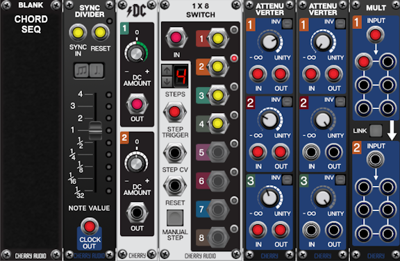
The CV output by the Chord Sequencer sub-system controls which input the four 8 x 1 switches in the Chord Generator sub-system select and the inputs of the switches are wired to multiple DC Source outputs that have been manually tuned to the scale of C major over two octaves.
You could retune the DC sources to another scale if you wanted. If you have LSSP XL then you could replace the DC Sources with a scale module and save a lot of manual fiddling about.
The switches work as a 4-pole 8-way switch and the wiring is done so that the eight switch positions correspond to eight different chords. The first switch (pole) on the left selects the root note, the next the third note, the next the fifth note and the final switch selects the seventh.
All the chords use four note stacks of thirds in the major scale so they produce the diatonic 7th chords – I7, ii7, iii7, IV7, V7, vi7. and vii dim7. As we are working in C the chords are therefore Cmaj7, Dm7, Em7, Fmaj7, G7, Am7, Bdim7. For simplicity everything is in close root position so this is crude doughnut balancing stuff in music theory terms, but it works well enough for the purposes of this patch. The top chord is just I7 but an octave higher than the one at the bottom of the sliders.
The chord progression as loaded is therefore vi7-iii7-IV7-I7. Or simplifying things 6-3-4-1. Because 7 x 7 x 7 x 7 is 2401 one might assume there are lots of permutations but many of these are redundant (2-3-4-1 is essentially the same as 1-2-3-4 and something like 1-1-1-1 doesn’t really count as a progression) so in reality there aren’t thousands of four-step diatonic 7th chord progressions.
Some common progressions you could experiment with are…
- 1-5-6-4,
- 6-4-1-5
- 1-4-5-4
- 1-6-4-5
- 2-5-1-6
- 1-6-4-5.
Returning to the practicalities of the patch, the four output voltages of the Chord Generator sub-system are fed to the labelled multiples on the right for distribution around the patch. The multiples are used to decouple the external wiring from the internal wiring of the sub-system.
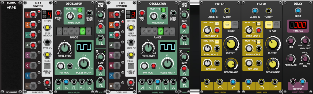
The Arps sub-system is a pretty simple but effective sound source that consists of just two oscillators fed through a high-pass/low-pass filter chain. The pitch of the oscillator on the left is determined by a switch that goes through a four-step cycle while the pitch of the oscillator on the right is determined by a switch that goes through a three-step cycle.
Both switches are clocked by the 1/4 note output of the Beat Generator sub-system.
The pitch CV inputs of the switches are hard-wired to the outputs of the Chord Generator. The left-hand oscillator’s pitch cycles through a pattern of the root, fifth, seventh and third of the current chord while the right-hand oscillator cycles through a root, fifth, third pattern.
| 1 | 5 | 7 | 3 | 1 | 5 | 7 | 3 | 1 | 5 | 7 | 3 |
| 1 | 5 | 3 | 1 | 5 | 3 | 1 | 5 | 3 | 1 | 5 | 3 |
So we end up with a three bar long cycle. However the chord progression changes once per bar in a four bar cycle so there is an interesting 3/4 ratio between the arp and chord progression cycles as well.
To add more subtle complexity the left-hand sawtooth oscillator has a tiny amount of vibrato added from an LFO and the right-hand pulse-wave oscillator has some pulse width modulation added from another LFO. Then both oscillators go through a high-pass filter with a cutoff frequency modulated by another LFO and then through a low-pass-filter modulated by a fourth LFO. All four LFOs operate at different frequencies producing a complex interplay. On top, the filter resonance of the high-pass filter is high enough to create some ringing. Then for good measure we add bright 300 ms delay with a good amount of feedback.
The Kick and Snare sequences are both driven at 1/8th note speed by a simple 1 x 8 switch. Both the STEP TRIGGER and IN inputs are fed the 1/8th clock from the Beat Generator. The Trigger to Gate module isn’t actually needed as the drum modules generate outputs even with a short trigger but it’s there in case you want to drive an envelope generator instead. The IN socket is fed the clock rather than just 5 V DC because we want adjacent on steps to trigger individual hits.
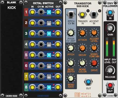
The kick and snare voices use the same mechanism with Octal Switches mapped to toggle buttons on the interface. Each switch connects an output from the 1/8th Beat Generator to the respective drum module.
An Envelope Follower is connected to the kick output so that we can do some side-chain processing on the root drone voice described shortly.
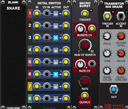
As mentioned earlier the Micro Burst module is used to add an optional flam to the snare.
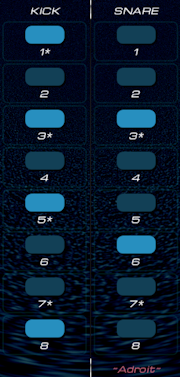
The interface buttons for the kick and snare sequencers use * symbols to indicate the most basic rhythm patterns. Four-on-the-floor for the kick and the backbeats for the snare. Elegantly shifting away from and back to these “home” patterns, especially to create simple fills, is something anyone interested in live performance might want to practice.
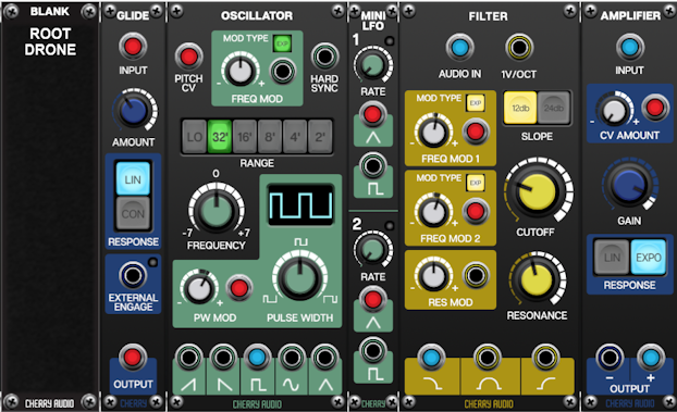
The Root voice is a drone that plays the root note of the current chord. The octave used is set by the OCTAVE slide-switch on the interface so we can get anything from a sub-bass to something that sounds like a slow melody. The glide module processes the voltage after the octave offset is added so you can get some manual portamento effects when the GLIDE knob is turned up and the OCTAVE slider is moved. The PWM toggle switches pulse width modulation on and off.
The KICK MOD knob controls how the kick drum’s volume profile affects the filter’s cut-off frequency. At 12 o’clock it has no effect. Clockwise settings add increasing amounts of modulation so a percussive kick causes the filter to open very quickly and then close slowly. Counter-clockwise settings negatively modulate the cutoff so the effect is that the filter closes quickly and opens slowly.
The Amplifier is used in the opposite was to how a VCA is normally used as the GAIN is turned up and the modulation is inverted. So the higher the CV the less signal passes through. As the CV is coming from the kick drum’s envelope follower the root voice ducks out of the way every time the kick plays to give us the classic compressor side-chain effect.
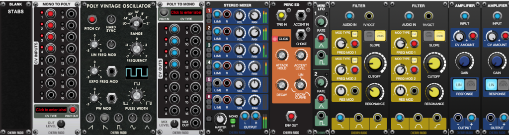
The Stabs voice plays the current four-note chord over and over at a pace determined by which button is selected on the interface. We’ve already discussed how the chords and timing elements are generated so here we’ll just look at the audio aspects.
The four individual pitch CVs come from the Chord Generator sub-system and are converted into a poly cable signal using the Mono to Poly module and fed to the Poly Vintage Oscillator. The NUMBER OF VOICES parameter on the Voltage Modular I/O Panel is set to 4 as otherwise we could be wasting CPU on oscillator voices that aren’t audible.
The sawtooth poly output from the poly oscillator is fed to a Poly to Mono module so that we can gain access to the four different signals in the monophonic domain. We could have used the MIX OUT signal from this module but it would be mono rather than stereo and as we have four different oscillator voices it would be nice to pan them to different stereo positions so a Six-Input Stereo Mixer is used. Another option would have been the Poly Stereo Spread module but this doesn’t allow us to customize the individual panning positions.
Because the signal is now stereo, two filters and two VCAs are used. A Percussion Envelope Generator is used to modulated the filters and VCAs and there are also two LFOs. If the STEREO LFO button on the interface is engaged then each filter has its own LFO and as these run at slightly different rates this adds movement in the stereo image as well as changes in timbre. If the STEREO LFO button is disengaged then the cutoff modulation for both filters uses the same LFO so there is no stereo motion, although the result is still sterero as each of the four oscillators is panned to its own position.
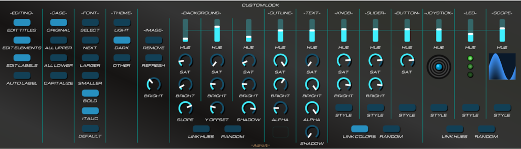
At the very bottom of the patch we have a Custom Look module that allows us to tailor the look of the interface. By being present in the patch these settings persist and reload whenever the patch is loaded.
The background uses an image rather then the default gradient-shading system that we’ve been relying on so far. It’s best to leave adding any image until you are broadly happy with the project as otherwise you may end up having to rejig the image file.
As the interface is a 10 x 2 array of Custom Panel modules the image was created with a canvas size that’s 10 x 172 pixels wide and 2 x 720 pixels high as described in the Custom Look documentation. The LOAD button was pressed and the 1720 by 1440 pixel image file located.
Unfortunately at present all of the Custom Panels’ horizontal and vertical indices need to be set correctly to get the image mapped correctly. This is very tedious to do manually using the right-click menus so check this link for a key-based shortcut.
I’ve put in a feature request for Cherry Audio to make available the coordinates of a module in the API so maybe one day this won’t be necessary. This feature would also allow for certain adjacent modules to link up automatically behind the scenes so would allow developers to create variable-sized extendable modules so I hope they add this simple feature at some point.
The BRIGHT knob in the Custom Look column that handles background images allows adjustment of the background’s brightness.

It only took me about 10 minutes messing around with the stock filters in paint.net to create this but you can use any graphics software you like to generate backgrounds. Spend some time exploring the noise rendering, distortion and colorizing filters you have available and obviously look at plugins if you want more scope.
Creating backgrounds that register with the controls requires a greater skill level, so I’d recommend you start with something simple and abstract like this background and work your way up.
Note that further in depth information is planned for the following new demos. In the meantime there’s some information about them on the Custom Scene Manager page.
Oram
This demo patch is named after Daphne Oram a pioneer in electronic music. Her Oramics system has had some influence on the design of Adroit Custom.
Click on the button below to download the .voltagepreset file.
Note that although this patch includes a scope beneath each motorized control these are not essential to the operation. They are just very useful visual aids when first exploring scene morphing.
To reset all the scene morphing data click on the Custom Scene Manager’s INIT button while holding down the SHIFT key.
Angels
The Angels patch demonstrates using Custom Scene Manager’s DISCRETE mode to morph between ten different vowel sounds. It was inspired by this vocal formant choir patch posted by Grant Middleton on Cherry Audio’s forum.
Click on the button below to download the .voltagepreset file.

You can select the vowel by clicking on the buttons with a mouse but it’s much more fun to “play” the vowels by pressing MIDI keys C1 through A1. Keys above A1 control which notes to play.
The results aren’t super realistic but it’s polyphonic and can produce some very nice synthetic cathedral style choir sounds. If you want to get really dramatic turn up the Morph Time, Detune and Resonance knobs and change vowels while playing dissonant chords. You should then be able to produce something similar to the epic György Ligeti sounds featured in 2001 : A Space Odyssey. Try the pitch bend and mod wheels too.
You can remap the buttons by right-clicking on them, selecting Relearn MIDI and pressing a MIDI key of your choice. You can also double-click on the text labels to change them to remind yourself which keys map to which vowels.
As the Arturia KeyStep is such a popular device there’s a version of the demo that’s mapped to its small keyboard. Click on the button below for the slightly different version intended for use with an Arturia Keystep.
In this version vowel selection is done via the keys F2 through D3.
Note that the knobs in these two patches are set to shared scene mode. So a change in scene (vowel selection) does not have any impact on them.
ZeroSeq
The ZeroSeq patch demonstrates combining Custom Scene Manger’s SEQUENCED mode with Custom Panel controls that are configured to use different numbered scene modes. The result is a 16-step sequencer with individual channels for pitch, volume, filter cutoff and filter resonance. It is called ZeroSeq because no sequencer module is used to achieve this.
Click on the button below to download the .voltagepreset file.

The color-coded RESET and NUDGE buttons on the left of the interface enable you to change 16 controls with a single mouse click.
Individually mapping the controls for all 16 steps would be extremely tedious and difficult to do by hand, but in practice all one needs to do is map the controls for step 1 and then use Adroit Custom’s intelligent cloning feature to automatically map the other 15 steps using a relatively small number of mouse clicks and key presses.
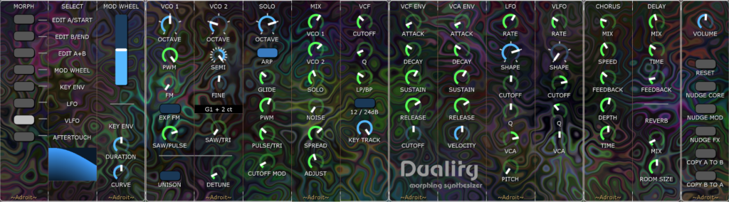
Duality Morphing Synthesizer
The latest and most sophisticated demo is called Duality. It has its own webpage here.