Table of Contents
Introduction
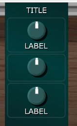
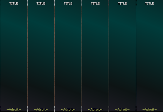
The Custom Panel module is at the heart of Adroit Custom.
When first added to a Voltage Modular patch it will look something like this…

This doesn’t look particularly exciting but Custom Panel has hidden depths and is in reality the most sophisticated of all Adroit Synthesis modules. So there’s a lot of information on this page!
It’s perhaps best to read the overview at Adroit Custom first and then treat this page as a reference manual.
Because so much of Custom Panel is menu-driven you should find that once you have a grasp of the basics, much of the functionality is discoverable by exploring the menus and experimenting. However, it’s worth skimming through this page just to get an idea of what information is available for when you do want to get into some specific detail.
Another piece of advice is to first look at using Adroit Custom without the Custom Scene Manager as this module adds a whole level of extra functionality on top of the basics.
A small custom interface might consists of just one or two Custom Panel modules but more typically you will use large numbers of them to form a composite panel that might span several cabinets.
The screenshots on this page use the default font, colors and styles but you can change the appearance of your interface drastically by using the Custom Look module.
Some of this documentation is shown in inverted colors (just like this paragraph). These parts refer to features of Custom Panel that are only relevant or available when the Custom Scene Manager module is present in a patch.
Title Area
At the very top of the Custom Panel module there is a special area just like on other Voltage Modular modules.
Normally when the mouse cursor is placed over this area it changes to a hand icon and you can then drag the module around, also a right-click in this area produces the standard Voltage Modular menu shown below.

If you select the Module Help option in this menu then your internet browser will display this page (providing that your computer is online).
The menu works in the usual manner so it doesn’t provide a mechanism to change the module’s TITLE text. To achieve this you need to engage the EDIT TITLES button that’s at the top of the EDITING column of buttons on the Custom Look module.
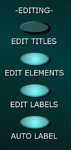
When the EDIT TITLES button is engaged you can double-click on the TITLE text of any Custom Panel module and enter your own text.
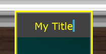
However, when the EDIT TITLES button is engaged you can no longer drag Custom Panel modules around, so you will usually want to disengage the button when you are done in order to return to the normal behaviour.
You might want to do title editing in batches – engaging the EDIT TITLES button, editing the titles of multiple Custom Panels and then disengaging EDIT TITLES.
Main Menu
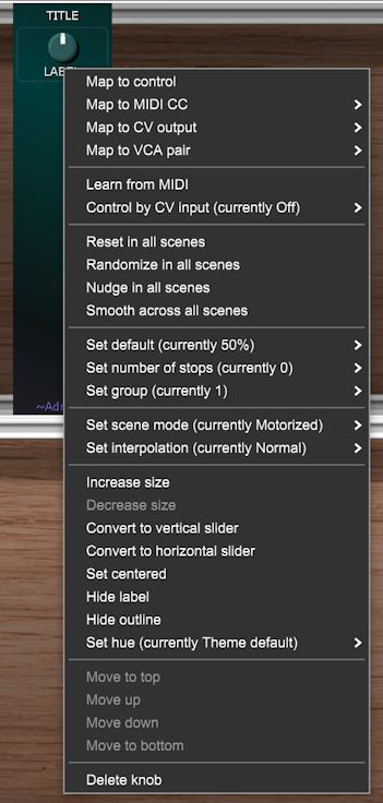
Providing that the EDIT ELEMENTS button on Custom Look is engaged then right-clicking on an empty part of a Custom Panel module launches its Main Menu…

Even when a Custom Panel is completely full of elements you can still launch this menu by right-clicking on the bottom of the module (where the ~Adroit~ logo is).
As you can no doubt see the main purpose of the Main Menu is to enable you to add knobs, sliders, buttons and various other elements to your custom interface.
As you add elements to a panel some of the options may be disabled as the menu only allows you to select options that are possible given the space remaining.
When the Custom Scene Manager module is present in a patch then the Add scene selector option becomes available in the Main Menu.
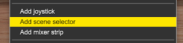
This option adds a minature version of the Custom Scene Manager’s Scene Selector to the panel.
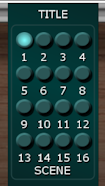
Mini Scene Selector
Knobs
Add small knob, Add medium knob, Add large knob
These options add a knob of a given size to the module.

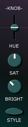
You can select different colors and styles of knob using the controls in the KNOB column of Custom Look.
These settings are generally common to all knobs but you can override the hue of individual knobs using the Set hue option in a knob’s right-click menu as described later.
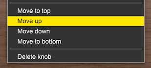
New elements are always added beneath any existing ones but you can rearrange the order by right-clicking on the element you want to move and selecting one of the Move options.
You’ll also notice that the last option in the menu lets you delete an element. If you accidentally delete an element or change its setting by mistake you can undo the operation with a CTRL Z (or ⌘ Z on a Mac).
Once added to a panel, a knob’s setting can be changed with a left-click vertical mouse drag just like regular Voltage Modular knobs.
For fine control hold down the CTRL (or ⌘) key at the same time.
For coarse control hold down the SHIFT key at the same time as dragging. This can be useful when you want to quickly change a knob to its minimum or maximum setting.
You can also randomize a knob’s setting by left-clicking on it while holding down the ALT key (or Option key on a Mac). This can be surprisingly useful when you want to quickly experiment with different settings.
A double-click returns a knob to its default setting. The default default setting is 50% but this can be changed by right-clicking on a knob and selecting the Set default menu option.

Special Reset buttons can be added to panels. When clicked they return all controls to their default setting (providing that a control’s group settings matches that of the Reset button). This works globally so a Reset button doesn’t have to be on the same panel as the controls it affects. More on groups and special buttons later.
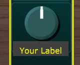
Beneath each knob there’s a text label. Providing that the EDIT LABELS button on the Custom Look module is engaged, you can double-click on this area and type in any text you like. If you are sharing your work internationally then another user might use this facility to translate labels into their own language.
There is obviously limited space so you should chose labels with care. You want something brief but descriptive. Also be aware that the font can be changed using Custom Look so you need to keep an eye on labels that fit using the original font but don’t when a different font is used.
As already mentioned, label editing is disabled if the EDIT LABELS button on the Custom Look module is disengaged. This prevents accidental changes and it also means that when your click is slightly off and you hit a label by mistake the label editor no longer annoyingly pops up.
If the AUTO LABEL button on the Custom Look module is engaged then labels are automatically generated for you when you map a control.
The result of auto-labelling depends on what the developer of a module called the mapped control inside their code and this name may often not be ideal, but it can still be useful, at least during the early stages of developing your own interface. You can of course always change the label with a double-click.
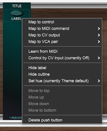
Knob Right-Click Menu
Providing that the EDIT ELEMENTS button on Custom Look is engaged then right-clicking on a knob or other element pops up a menu with a range of options…

When the Custom Scene Manager is present in a patch this menu expands to include more options.
Expanded menu
We’ll spend a lot of time discussing the knob’s right-click menu as most of what applies to knobs also applies to the other types of elements (particularly sliders which are in effect just linear rather than rotary knobs).
Map to control
Perhaps the most important option in a knob’s right-click menu is Map to control. When this option is selected all of the things in your patch that the knob could control will be highlighted in green as shown in the example below with a stock Filter module.

Press the escape key or click on any part of the Custom Panel module if you need to abort this mapping operation.
If you click on the Filter’s CUTOFF knob then the Custom Panel knob will control the CUTOFF knob.

Notice that the setting of the Custom Panel knob has changed to match the existing setting of the CUTOFF knob and because the Custom Look AUTO LABEL button was engaged the label beneath the Custom Panel knob has changed to the name that Cherry Audio used for the CUTOFF knob when they were developing their Filter module.
It seems they chose to call it “Cutoff Frequency”. This is too long a name to fit in the limited space available but it’s still useful for tracking what is going on. You can quickly fix this minor problem by double-clicking on the label and typing something shorter like CUTOFF.

If the AUTO LABEL button on Custom Look wasn’t engaged when you performed the mapping then the label would not have changed.
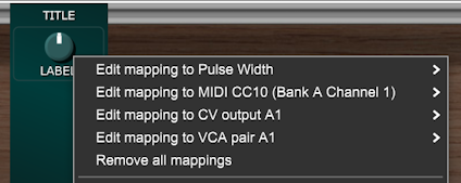
Now that a control mapping is established you can edit the mapping by right-clicking on the knob and selecting Edit mapping to Cutoff Frequency.
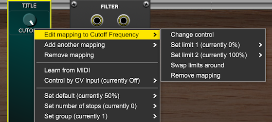
The Change control option allows you to select a different control as the target.
The Set limit 1 option lets you specify what setting the target control has when the custom knob is at its minimum (fully CCW) setting.
The Set limit 2 option lets you specify what setting the target control has when the custom knob is at its maximum (fully CW) setting.
These limits are expressed as percentages relative to the target control’s range of settings.
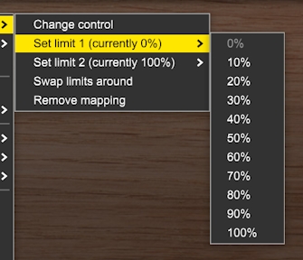
By default Limit 1 is 0% and Limit 2 is 100%. This means that there is a straightforward one-to-one mapping with the target control’s setting being the same as the custom knob’s setting. This is typically what you want but you have have the option of making the target knob vary over a smaller range or in the opposite direction.
Reversed mapping, where you want a target knob to rotate in the opposite direction to the custom knob, is sufficiently common that there is a Swap limits around option that makes this very easy to set up.
Remove mapping breaks the link between the Custom Panel knob and the target.
Map to MIDI CC
A second type of mapping allows MIDI CC messages to be transmitted via a Custom IO module’s MIDI OUT socket whenever the knob’s setting is changed.

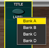
After selecting which Custom IO bank to use and which MIDI channel to transmit on, another menu lets you choose which of the 128 CCs to use.
There are 4 separate MIDI outputs available each with 16 channels and each channel supports 128 different CCs so in theory at least you should be able to individually map every parameter in a studio even if you have a lot of MIDI gear.
If auto-labelling is enabled then the label will change to indicate which CC the knob has been mapped to.

Note that push buttons have different MIDI mapping options. They can for instance send Program Change messages so that you can change the patch selected on an external synthesizer by clicking on a Custom Panel button.
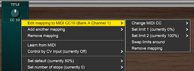
As with mapping to a control you can edit a MIDI CC mapping via the knob’s right-click menu as shown below.
Map to CV output
Another mapping type is Map to CV output. This makes a knob control the voltage available from a CV OUT socket on a Custom IO module.
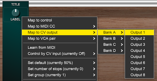
Up to 32 of these outputs are available (8 in each Custom IO Bank). You can use these outputs to control anything in your patch that responds to control voltages. If you have a suitable DC coupled audio interface then you could send up to six of these CV signals out to Eurorack via Voltage Modular’s AUX OUT to host sockets.
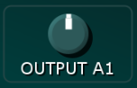
If auto-labelling is enabled then the knob’s label will change automatically…
CV outputs provide an alternative mechanism for controlling parameters in your patch. Sometimes it makes sense to map to a control while sometimes it’s better to use CV.
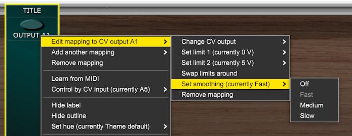
You can edit a CV output mapping via the knob’s right-click menu as shown below.
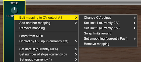
When a knob is mapped to a control or MIDI CC then the Limt1 and Limit 2 values are expressed in percentages but when a knob is mapped to a CV output they are expressed as voltages.
This means you can set up various useful voltage ranges without having to use Attenuverter or DC Source modules to scale and offset the CV.
By default limit 1 is set to 0 V and limit 2 is set to 5 V but there are lots of other options available. The cents and semitones options produce the desired voltages when standard 1 V per octave voltage control of pitch is used.
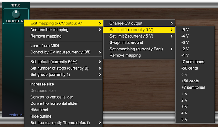
You will often want to combine the use of voltage ranges with the set number of stops option discussed later as this enables you to change knobs into rotary switches that select specific and precise voltages or pitches.
Along with the more usual options found when editing mappings there is a means to Set smoothing but this only applies when the Custom Scene Manager module is present in a patch.
Map to VCA Pair
A fourth mapping type is Map to VCA pair. This enables a knob to control the gain settings of a pair of VCAs in a Custom IO module. These VCAs can perform various utility functions in your patch.
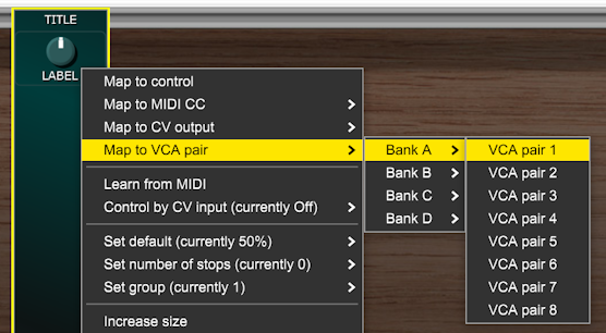
There are a maximum of 32 VCA Pairs available (8 in each Custom IO Bank). Often you will only use a single VCA but they are paired in order to support things like stereo volume control, crossfading and panning.
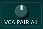
On mapping, if auto-labelling is enabled then the knob’s label will change automatically…
Once a VCA mapping is established you can edit the mapping via the right-click menu. The key option here is Set VCA pair type.
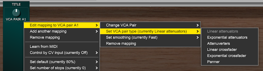
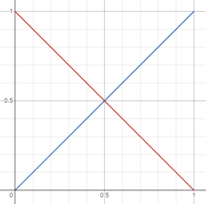
Linear attenuators configures the knob to control the gain of both VCAs in a linear fashion. The gain is 0 when the knob is fully CCW and 1 when fully CW. Gain at 12 o’clock is 0.5.

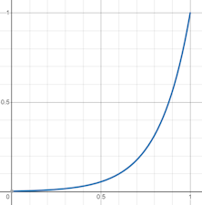
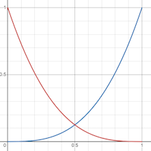
Exponential attenuators similar to the linear attenuator mode but the control uses the exponential curve shown below and is therefore more suitable for things like volume control. Gain at 12 o’clock is approximately 0.05625.
Attenuverters provides dual linear attenuvertors. Gain is -1 when the knob is fully CCW and 1 when the knob is fully CW. Gain at 12 o’clock is 0.

Linear crossfader the left VCA operates as a linear attenuator while the right VCA’s gain is the inverse (1 – gain).
Exponential crossfader as linear crossfading but with cubic curves.
Panner this uses sine pan law.

Note that the Set smoothing option is only relevant when the Custom Scene Manager is present in a patch.
Multiple mappings
Usually you’ll want a knob in your custom interface to control just one thing in your patch but you can set up to four different mappings at once. So turning a single knob on your interface can adjust several other knobs or sliders at different speeds and in different directions. You can use a mixture of mappings too – so a single knob could control another knob, transmit MIDI CC messages, output a CV voltage and control a VCA Pair all at the same time.
Learn from MIDI
Learn from MIDI enables a knob to be controlled by MIDI CC or MIDI note on messages fed to the MIDI IN socket of a Custom IO module.
Learn from MIDI only works when there is a Custom IO module in the patch that is set to Bank A.
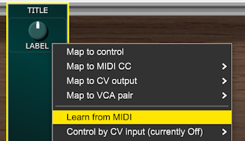
On selecting Learn from MIDI a message box appears over the knob and the module waits until a MIDI message is received.
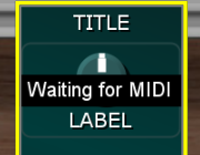
Press the escape key or click on any part of the Custom Panel module if you need to cancel a MIDI learn operation.
When a MIDI CC or a note on message is received the knob remembers which MIDI Channel it was on and which CC number or note it was and subsequent messages that use the same CC or note control the control. So for instance if you want the Mod Wheel on a keyboard to control a particular knob in your interface then select Learn from MIDI in the knob’s menu and move the Mod Wheel slightly. The Mod Wheel will then control the knob.
Only the MIDI IN of the Custom IO module designated as Bank A accepts MIDI input. This should be sufficient as Voltage Modular performs MIDI merging when multiple MIDI cables are patched into the same input. So if you need to mix two MIDI streams together simply plug both cables into the MIDI IN socket on Bank A.
The MIDI IN socket is normalled to the MIDI FROM HOST output on Voltage Modular’s I/O Panel so you usually don’t need to use a cable if the MIDI is coming from there. However, if the MIDI is coming from somewhere within your patch then obviously a cable is required.
Control by CV input
The Control by CV input option allows a knob to be controlled by CV from a Custom IO CV IN socket.

Adroit Custom maps 0 V to a knob’s fully CCW position and 5 V to its fully CW position. Voltages outside this range are clamped.
When a knob is being controlled by CV input you will no longer be able to set it manually as any manual setting will constantly be being overriden by the CV. Although this might change in a future update as it would be useful if you could do manual override when the voltage was constant.
Being able to control a knob with CV offers a great deal of flexibility as CV can come from so many different sources and a knob can be mapped to up to four different targets. Even if you can’t manually alter the knob it provides visual feedback and its right-click menu provides a means to configure the mapping.
The image below shows how you might use a Super LFO module that is tempo synced to cycle once every 1/4 note to alter a knob’s setting.
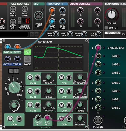
When using a Super LFO make sure its POLARITY knob is set full CW so that it generates a unipolar 0 V to 5 V signal.
The “all scenes” options are only accessible when the Custom Scene Manager is present in a patch.
Reset in all scenes, Randomize in all scenes, Nudge in all scenes

These options reset, randomize or nudge a knob’s setting in all 16 scenes.
Smooth across all scenes

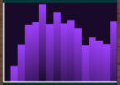
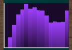
The Smooth across all scenes option performs an averaging operation on a knob’s settings across adjacent scenes. It’s rather like applying a low-pass filter that irons out sharp differences. It can be applied once or multiple times to achieve the desired amount of smoothing. The View inside control scope images below show a randomized set of values for a knob’s 16 scenes being repeatedly smoothed.


Set default
The Set default option lets you specify a default value for a knob.
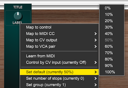
A knob is set to this value when you double-click on it. The default value is also used when a special Reset button with a group that matches the knob’s group is pressed.
A knob is also reset to its default value when the INIT Scene Operation button on a Custom Scene Manager is pressed providing that the knob’s group matches the Custom Scene Manager’s group setting.
Set number of stops
This option allows a knob to have its number of stops set. When the number of stops is 0 a knob is continuously variable but when stops are set there are a limited number of control positions. In effect it turns the knob into a rotary switch. This can be very useful for precise control.
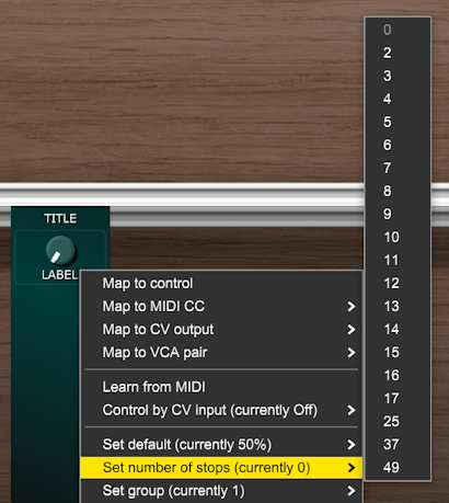
As an example a knob could be mapped to CV output with this CV being sent to a VCO’s 1 volt per octave pitch control input. Then if Limit 1 is set to -2 V and Limit 2 set to +2 V and the number of stops is set to 5 we end up with a 5 position rotary switch that has -2, -1, 0, +1 and +2 octave settings.
When a knob has stops set then markings are drawn to indicate where the stops are.
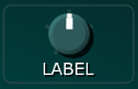
These markings can be almost invisible as shown above or more obvious depending on the OUTLINE settings on Custom Look.
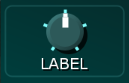
The Outline ALPHA knob doesn’t affect stop markings so it’s possible to turn down the alpha setting so that outlines are almost invisible while the stop markings stand out.
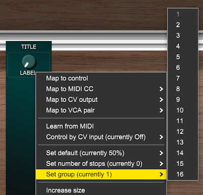
Set group
This option allows you to assign a knob to one of 16 groups. Groups are used to limit the effect of certain special buttons such as Random, Nudge and Reset. These will only have an impact on a knob if they have a matching group setting. So for instance you could add a Random button to your interface that only randomizes knobs that are in group 2.
Increase size, Decrease size
The Increase size option allows small and medium sized knobs to be made larger providing that there is sufficient vertical space remaining.
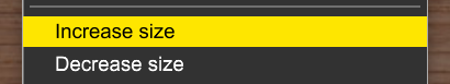
The Decrease size option allows medium and large sized knobs to be made smaller.
Convert to vertical slider, Convert to horizontal slider
These options allow you to change a knob into a slider.

The smallest slider is taller than the smallest knob so in rare situations these options might be disabled due to lack of remaining vertical space.
Set Centered, Set Not Centered
These options allow you to specify whether a knob or slider has a central origin. This only affects the graphical appearance of a control and only then in certain styles (as set by the Custom Look module). An example of a centered knob might be one used for panning. Most of the time you’ll want the default not centered setting.

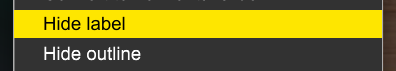
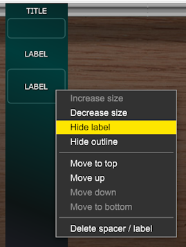
Hide label, Show label
The Hide label option hides the text label that’s normally beneath a knob and frees up the space it uses.
If the label is already hidden you’ll see a Show label option instead although this will be disabled if there isn’t sufficient vertical space available.
Hide outline, Show outline
The Hide Outline option hides the rounded rectanglular outline drawn around elements. If the outline is already hidden then you’ll see a Show outline option instead.

Outlines add a little bit of decoration and can be subtle or obvious depending on the OUTLINE setttings in Custom Look. They are helpful when you are new to using Adroit Custom as they make the extent of elements obvious but you may prefer a less cluttered look and want to remove them. A quick way to hide all outlines is to set the Outline ALPHA knob on Custom Look to its minimum setting.
Set hue
This option defaults to Theme default where everything about the knob’s appearance is determined by the currently selected theme on the Custom Look module, but you can override this to give a knob a different hue.
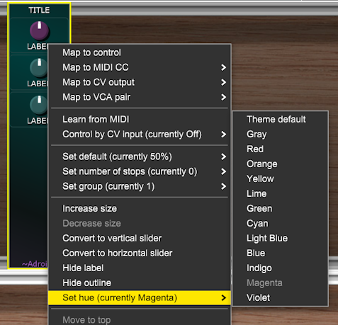
The saturation, brightness and style parameters are still set by Custom Look. Although very low settings of saturation and brightness are ignored as otherwise the hue set here wouldn’t have any visual impact (given that very low saturation turns colors monochromatic and very low brightness makes everything look black).
Remember that when you have set a knob’s hue using this override method it will no longer be affected by Cutom Look’s KNOB HUE slider.
Sliders
Add small vertical slider, Add medium vertical slider, Add large vertical slider, Add huge vertical slider
These options add vertical sliders of various sizes to the module.
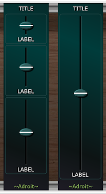
As you can see the huge slider really is huge – taking up an entire Custom Panel module by itself. You might not use this very often but it is handy in certain applications.
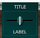
Add horizontal slider
This options adds a horizontal slider to the module.
Sliders work in essentially the same way as knobs. So virtually everything said about knobs also applies to sliders.
One big difference between Adroit Custom sliders and the regular Cherry Audio ones is that they don’t jump when you click on them – to change their setting you need to drag the mouse up or down (or left or right in the case of a horizontal slider).
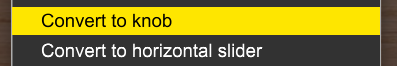
Convert to knob, Convert to horizontal slider, Convert to vertical slider
These options allow you to convert between vertical sliders, horizontal sliders and knobs.
Push Buttons
Add push button
This option adds a momentary action push button to the module.

A lot of what has been discussed in regards to knobs and sliders also applies to buttons but obviously buttons only have two states so some things are simpler.
Push buttons don’t have any “memory” as they are disengaged by default and are only engaged when you click on them or a MIDI message or CV control causes them to be engaged.
When you right-click on a push button the following menu pops up.
Map to Control
As with knobs and sliders, when you select the Map to control option all of the things in your patch that the push button could control will be highlighted in green. You can then click on the target you want the button to control.
Press the escape key or click on any part of the Custom Panel module if you need to abort this mapping operation.
Normally you’ll map a push button to a button but, although it’s not particularly useful, you can map one to a knob or slider instead. When the target is a knob or slider the target jumps between the Limit 1 and Limit 2 settings.
Map to MIDI command
As push buttons have a monentary action they transmit command style messages rather than CC.
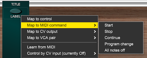
As with other MIDI message transmissions the messages are sent to a MIDI OUT socket on a Custom IO module. So on selecting a command a menu appears asking which Custom IO Bank to send the message to.
Start transmits a MIDI start message when the button is pressed. Stop transmits MIDI stop and Continue transmits MIDI continue. These options enable you to add buttons to your custom interface that control the transport of MIDI sequencers.
Program Change transmits a MIDI program change message when the button is pressed. This enables you to add buttons to your interface that change the patch on any connected MIDI kit. A series of menus pop-up so that you can select the Custom IO Bank, MIDI Channel, MSB, LSB and Program number.
All notes off transmits a MIDI all notes off message and is useful if any MIDI notes get accidentally stuck on during rewiring.
Map to CV Output
This option works in the same way as with knobs and sliders except there’s obviously only two states. Also the Set smoothing option has an impact even when Custom Scene Manager isn’t part of a patch because sometimes we may want a smooth transition in voltage rather than an instant change.
The image below uses four scopes to show how the smoothing setting affects the CV output.
It’s a little easier to see what is happening if we use CV Watcher to look at the curves, as the difference between some of the settings is quite subtle.

Map to VCA pair
Again this option works in more or less the same way as with knobs and sliders, but the smoothing option can be even more useful than with mapping to CV as we will often be switching audio signals using the VCAs and instantaneous changes in gain will cause clicking and popping artifacts.
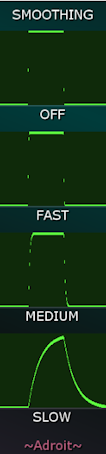
So with smoothing set to Off there will be nasty artifacts, Fast is just slow enough to remove the bulk of these, Medium removes them but the response is a little sluggish, while Slow gives a distinct fading effect.
Fast is the default setting as it is generally a good compromise.
Learn from MIDI
When a key controls a push button the button is enaged while the key is pressed. When a CC is used the button is enaged while the CC value is 64 or above.
Learn from MIDI only works when there is a Custom IO module in the patch that is set to Bank A.
Control by CV
When CV controls a push button it is engaged when the voltage is 2.5 V or above.
Toggle and Radio Buttons
Add toggle button, Add radio button
These options add a toggle button or a radio button to the module. Both look exactly the same as push buttons but unlike push button, toggle and radio buttons have a “memory” – they are either engaged or disengaged and this state is stored so that when you reload a patch they have the same state they had previously.
While toggle buttons are independent of one another, only one radio button on a Custom Panel can be active at a time (rather like the buttons found on old-fashoned radios).
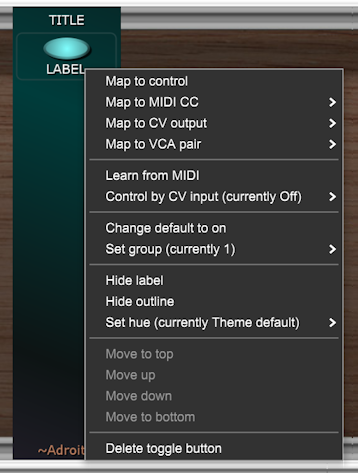
When you right-click on a toggle or radio button you’ll get a menu that’s the same as the push button one except that Map to MIDI command is replaced with Map to MIDI CC.
When a radio or toggle button is mapped to CV then Limit 1 specifies the output voltage when the button is disengaged and Limit 2 the voltage when it’s engaged just as with push buttons.
When a radio or toggle button is mapped to MIDI CC then Limit 1 specifies the CC value when the button is disengaged and Limit 2 when it’s engaged. These values are in percentages of 127. So by default the MIDI CC is 0 or 127 but if you say set Limit 1 to 10% and Limit 2 to 90% the CC values would be 12 and 114.
Learn from MIDI
When a key controls a toggle button then each press of the key toggles the button’s state. If a button on a MIDI control surfaces transmit a value of 127 when pressed and 0 otherwise on a particular CC then this is treated the same way as a key so that each press of the MIDI button flips the toggle button between states.
Radio buttons controlled by keys and MIDI buttons change state as you’d expect so if say one radio button responds to the key F2 and another to G2 then pressing F2 will engage one and G2 will engage the other. And if you have one MIDI button that transmits on CC1 and another that transmits on CC2 then they’ll control radio buttons that respond to CC1 and CC2 as expected.
Learn from MIDI only works when there is a Custom IO module in the patch that is set to Bank A.
Control by CV
Currently toggle and radio buttons react to CV control in the same manner as push buttons but this might change in a future update so that they change state on detecting rising-edge triggers.
Special Buttons
Add special button
The Add special button option adds a special push button to the module. A submenu lets you choose the type of special button you want.

When the Custom Scene Manager is present in a patch this menu expands to include more options.
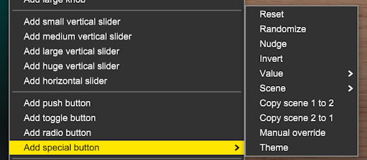
Expanded menu
The Reset, Randomize, Nudge, Invert and Value special buttons all have a group parameter. This parameter limits the scope of the button’s effect to only those other controls that have a matching group set in their right-click menus.
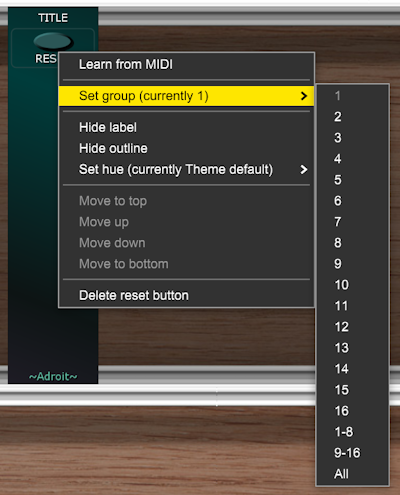
As well as being able to target one of the specific 16 groups there are also three multiple group options 1-8, 9-16 and All.
1-8 affects all controls that are in groups 1 through 8. 9-16 affects all controls that are in groups 9 through 16, Finally All affects all controls regardless of their group setting,
Special buttons themselves are not affected by other special buttons.
Reset buttons reset the setting of controls in their target group to their default values.
Randomize buttons randomize the settings of controls in their target group.
Nudge buttons are similar to Randomize buttons but they take into account the existing setting of their targets and apply a small random adjustment to the old values. This is very useful for creating slight variations.
Invert buttons invert the settings of their target controls. So if a target is a knob or slider its setting will be adjusted to be a mirror about its central value (for instance a knob set at 9 o’clock will flip to 3 o’clock). If a target is a toggle button it will switch to its opposite state.
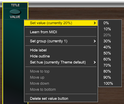
Value buttons have a submenu that enables you to choose a value to set their targets to. This can be selected when the button is added or changed later using its right-click menu as shown below…
These special buttons have global impact – they can change the settings of controls in any Custom Panel module, not just the one they are part of.
If you hold down the SHIFT key while clicking on a Reset, Randomize, Nudge, Invert or Value special button then the operation is applied to all 16 scenes rather than just the currently active one. See the Custom Scene Manager documentation for more details.
The Theme button cycles through the LIGHT, DARK and OTHER themes configured by Custom Look.
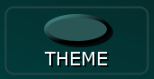
It provides a simple way to change the theme without having to use the buttons on the Custom Look module.
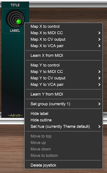
Joysticks
Add joystick
This option adds a joystick to the module.

Joysticks have two dimensions but otherwise behave in a similar manner to knobs and sliders. They are particularly good in live situations when all you have is a mouse, as they give you two degrees of freedom instead of just one
The horizontal axis is labelled X and the vertical axis is labelled Y.
As with knobs and sliders the CTRL (or ⌘) key gives fine control, ALT (or Option) does randomization and double-clicking causes a reset to default.
However, the SHIFT key is ignored as accelerating the motion just doesn’t feel right. Also there’s no option to set defaults other than the center position. This simplifies the joystick right-click menu a tiny bit too as it already has a large number of options due to the extra dimension…
Mixer Strips
Add mixer strip
This option adds a ready-made mixing element to the module.
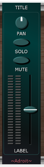
Like the huge slider, this element takes up the entire module.
The mixer strip is designed to simplify the construction of modular mixing systems. Each mixer strip controls its own VCA Pair on a Custom IO module and the idea is that you can then wire up the VCAs in whatever configuration you want.
Its right-click menu looks like this…
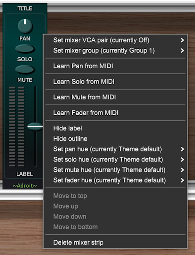
The Set mixer VCA pair option is key here as it lets you specify which VCA Pair is being controlled by the mixer strip.
VCA Pairs are, as the name suggests, just two Voltage Controlled Amplifiers that are configurable in various ways. They have already been discussed in the section above on mapping knobs to VCA pairs and are also covered in the Custom IO documentation.
The image below shows what a VCA Pair looks like.
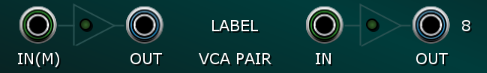
The two sockets on the left are the input and output of the left-hand VCA and the two sockets on the right are the input and output of the right-hand VCA.
If nothing is connected to the right-hand VCA’s input then it receives a copy of the left-hand VCA’s input. So you can use the IN(M) socket on its own as a mono input or use both input sockets for stereo operation.
When a VCA pair is controlled by a mixer strip the gain settings of the two VCAs are determined by the mixer strip’s fader, PAN, SOLO and MUTE control settings.
The LED meters on the mixer strip are Peak Programme Meters with each bar representing 2 dB. They measure the outputs of the VCA Pair so they show the signal strengths after the fader and pan controls have had their influence.
0 dB in Voltage Modular equates to a +/- 5 volt peak-to-peak signal but some modules clip above this point so it can often be important to track levels. At this point, rather than go into lots of technical detail, all you really need to know is that it’s best to avoid the meters going into the red too often.

The MUTE button silences a channel while the SOLO button silences any other channels in the same mixer group that aren’t also soloed. When both MUTE and SOLO buttons are engaged at the same time the SOLO function wins.
The PAN knob controls panning when the input is mono or balance when the input is stereo.
The mixer group setting is provided so that you can use multiple mixers in a project or construct mixers with group capabilities without the SOLO buttons in different mixers or groups interfering with each other.
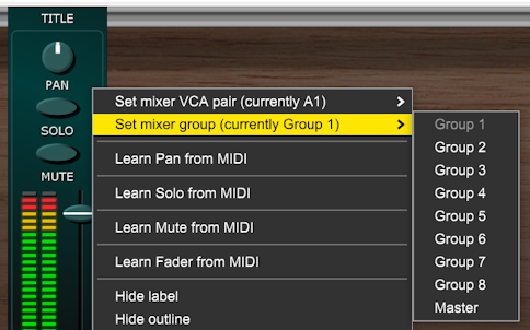
If the mixer group is set to Master then the mixer strip doesn’t have a SOLO button and is unaffected by the state of solo buttons on any other mixer strips.
In a simple mixer setup you’ll have a mixer strip and a VCA pair for each channel in your mixer and sum the outputs by patching all of the VCA left outputs to one destination and all of the VCA right outputs to another in order to create a stereo master output.
See the Simple Mixer project on the Adroit Custom Demo Patches page for more practical details and to download an example preset.
LEDs
Add LED
This option adds a simulated Light Emitting Diode to the module.

By default the brightness of the LED is controlled by the voltage fed to the IN 1 socket of the Bank A Custom IO module but this can be changed in the right-click menu.

Zero volts and negative inputs result in an unlit LED while higher voltages result in progressively more bright illumination up to full brightness at 5 V and above.
The Scene N gate options in the input submenu are only relevant when Custom Scene Manager is used so please ignore them for now.
Scopes
Add small scope, Add medium scope, Add large scope
These options add an oscilloscope (or ‘scope for short) of a given size to a module.
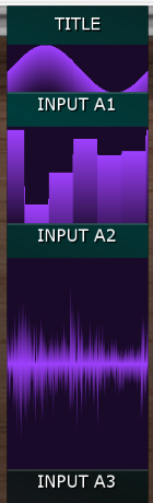
Visualization can really help us to understand what is happening inside a patch so scopes are an important tool in Adroit Custom. For instance it’s useful to be able to see what an ADSR envelope generator’s output is doing in response to its gate input and settings.
Scopes impact on performance more than other elements, although not ridiculously so. When using many scopes at once keep an eye on CPU and GPU use just so that you have a feel for their cost.
The right-click menu for a scope lets you specify a type and an input.

Bipolar and Unipolar scopes are mainly intended for looking at control voltages. Bipolar scopes show voltages in the range -5 V to 5 V. Unipolar scopes show voltages in the range 0 V to 5 V. Waveform scopes have the same range as bipolar ones but display the deviation from 0 V so are more suitable for looking at audio waveforms than CV. They don’t show waveforms at the individual cycle level but are still useful for checking for problems such as clipping and DC bias.
All three of these scope types show a one second long window of time and get their data from an input socket on a Custom IO module.
The View inside control above and View inside control below scope types are quite different. They allow you to see some of the inner workings of Adroit Custom when the Custom Scene Manager is present in a patch. The only difference between the above and below versions is which neighbouring element the scope is inspecting.
Pitch Meters
Add pitch meter
This option adds a simple pitch meter to the module.
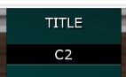
Pitch meters are just specialized voltmeters that take a control voltage from a Custom IO input and display what pitch that voltage represents in a 1 V per octave system where 0 V equals C2. So the image above shows what a 0 V input would produce.
The image below shows a pitch meter being fed the voltage representing F#3.
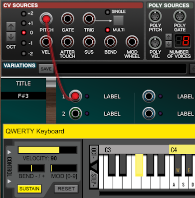
The main application for the pitch meter element is to display a VCO’s tuning. It’s a workaround for the fact that Custom Panel modules don’t display tootltips (because they don’t normally have access to the information required to provide meaningful tooltips) yet VCO tuning is perhaps the one situation where we really need tooltip style feedback.
Here’s a typical scenario where we have knobs for setting a VCO’s octave, semitone and fine tuning offsets…

The pitch meter in the image above is showing that the net effect of the three knobs is to produce a base tuning of D4 with +5 cents of fine adjustment.
The patch below shows how to implement this.
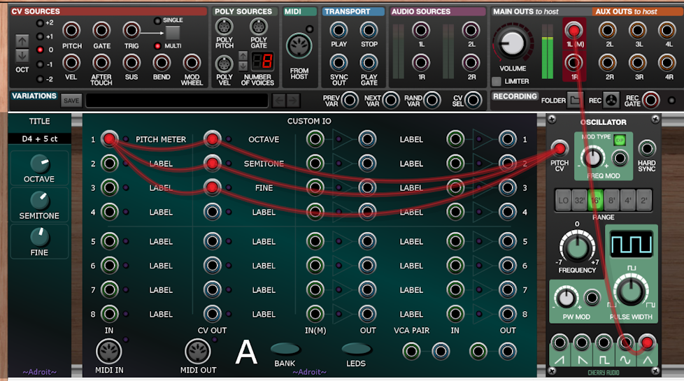
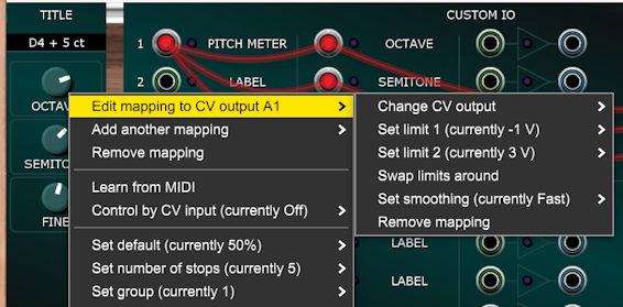
The OCTAVE knob is configured (via its right-click menu) to output a voltage to the A1 output using 5 stops with limits of -1 V and 3 V. So it functions as a five position rotary switch with settings of C1, C2, C3, C4 and C5.
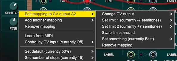
The SEMITONE knob is configured to output a voltage to the A2 output using 15 stops with limits of -7 semitones and +7 semitones. So it functions as a 15 position rotary switch with semitone steps and a zero offset at 12 o’clock.
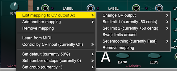
The FINE knob is configured to output a voltage to the A3 output using no stops and with limits of +/- 50 cents.
The pitch meter is set so that its input is from the A1 input which is fed the sum of the A1, A2 and A3 outputs via the three cables. The oscillator’s PITCH CV is fed the same voltage. In practice another cable would also be patched to the oscillator’s PITCH CV input that added the desired pitch offset voltage from a keyboard or sequencer etc.
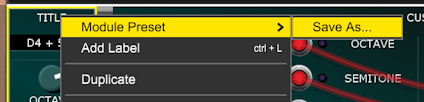
This arrangement is one you might use over and over in projects so it’s an ideal candidate to be saved as a Module Preset by right-clicking on the Custom Panel’s title area…
This tuning arrangement is used for the VCOs in the Mono Synth project on the Adroit Custom Demo Patches page.
An alternative approach would be to use radio buttons mapped to the oscillator’s “footage” buttons rather than use the OCTAVE knob and to map the SEMITONE knob to directly control the oscillator’s FREQUENCY knob but the CV based approach shown uses less space and includes the helpful tuning readout at the top.
Graphics
Add graphic
This option adds a graphic to the module that’s displayed over the background. It’s intended for adding things like logos to your interface.

The image is loaded from a standard PNG, JPEG, GIF or BMP file but the data is then stored inside the Voltage Modular preset file so the original file is no longer required. Transparency is supported so if the image contains transparency information the background can show through parts of the graphic as shown above.
Note that all graphics in Adroit Custom are handled at twice the regular resolution and then shrunk down to fit. This is done so that the graphics remain crisp if magnified.
Graphic elements are stored internally as images that are 172 pixels wide and 160 pixels high but the original image file can be any width and height as it will be stretched or squashed to fit. The graphic shown above came from a random free download file that happened to be 480 by 480 pixels and as you can see it works fine, but for precise results it’s best if your original file is 172 pixels wide and 160 pixels high.
No padding is added above or below graphic elements. This means that if you butt several graphic elements together vertically there will be no visible seams. The maximum number of graphic elements that will fit inside one module is four so by chopping an image into 160 pixel high slices you can display images that are either 160, 320, 480 or 640 pixels high.
Graphics take up the full width of the Custom Panel module so you could also horizontally slice a wide image and display it in pieces across several modules. There will be a seam visible as you can’t avoid the slight gap between modules but it can still look good. However, if you want to customize the entire background of your interface it’s easier to just use one large file for the background as described in the Custom Look documentation.
Spacers / Labels
Add small spacer / label, Add medium spacer / label, Add large spacer / label
These options add elements that consist of an outline, a text label, both or just a blank space. They give you a bit more flexibility when designing the layout of your interface.
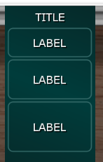
Having elements that initially are invisible would be very confusing so by default both the text label and outline are visible, but you can hide either or both using the element’s right-click menu.
Other Main Menu Options
Set horizontal index, Set vertical index
If you look at the shading patterns in some of the images above then you may be wondering how Adroit Custom seems to “know” the layout of the modules. Well the answer is it doesn’t. I’ve requested that Cherry Audio make this info available via the API in a future update as modules knowing where they are in relation to their neighbours would be very useful but for now you need to tell Custom Panels where they are in the layout.
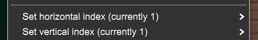
The horizontal index locates a module horizontally and the vertical index locates it vertically. So in an interface that’s five modules wide by two cabinets high the indices would look like this…
| 1, 1 | 2, 1 | 3, 1 | 4, 1 | 5,1 |
| 1, 2 | 2, 2 | 3, 2 | 4, 2 | 5,2 |
When there are only a small number of Custom Panel modules in your interface it’s easy to set the indicies manually, but with larger interfaces it can become something of a chore but the cloning tool discussed in detail in the keyboard shortcuts section below helps by automating some of the process.
Set background hue
This option allows you to change the hue of a Custom Panel module background to something other than the hue set by the three background hue sliders of the current Custom Look theme.
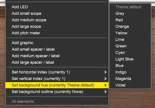
It works in a very similar way to the Set hue option in the right-click menu for elements like knobs as it overrides the hue set by Custom Look. The saturation and brightness set by Custom Look are still used, as are the SLOPE and Y OFFSET shading parameters.

The Set background hue option is useful if you want to make one or two panels stand out from the rest but don’t want to go to the trouble of using a custom background image. An more subtle alternative is the background outline feature described below.
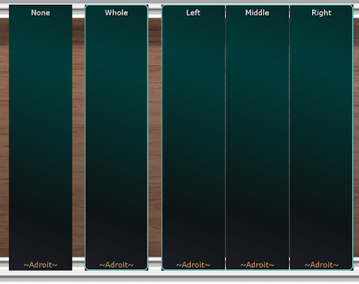
Set background outline
This option allows you to add some edge decoration to Custom Panel that help illustrate functional groupings in a large interface. You’ll only use this feature when you have a fair number of panels butted together horizontally and you want to show that they are divided into sections.
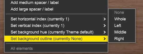
It’s a fairly subtle effect and only really visible when the Custom Look outline color is prominent, but in the correct context it’s very useful.
The Duality demo uses background outlines to show how the panel is divided into sections.
All elements
This option allows you to perform certain bulk operations on all of the elements of a Custom Panel module.
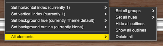
The Set all groups option is a shortcut for right-clicking on each of the elements and using their Set group option.
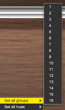
Note if you want to make a special button target multiple groups i.e. 1-8, 9-16 or All this must be done using the individual button’s menu.
The Set all hues option is a shortcut for right-clicking on each of the elements and using their Set hue option so that they all have the same hue.
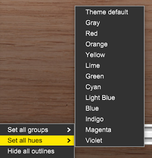
The Hide all outlines option is a shortcut for right-clicking on each of the elements and selecting Hide outline.
The Show all outlines option is a shortcut for right-clicking on each of the elements and selecting Show outline.
The Delete all option deletes all of a module’s elements. If you accidentally delete everything by mistake you can undo the operation with a CTRL Z (or ⌘ Z on a Mac).
Keyboard Shortcuts and Intelligent Cloning
CTRL J (or ⌘ J)
Often you’ll want to add multiple instances of the same type of element to a Custom Panel to create a column of knobs or buttons for instance. The CTRL J (or ⌘ J on a Mac) keyboard shortcut helps here.
Let’s say you want to create a column of five toggle buttons. You could add each one by right-clicking and selecting Add toggle button but it’s quicker if you add just one button using the menu then hold down the CTRL (or ⌘) key and press the J key four times.
This shortcut duplicates whatever element is at the bottom of the module (providing there is sufficient space). Most of the element’s properties are copied too, so if for instance the existing element has its label and outline hidden then any duplicated element will also have its label and outline hidden. Mapping information is not copied though.
CTRL C (or ⌘ C)
This copies all of the information about the currently selected Custom Panel module to a cloning clipboard.
When a module is selected Voltage Modular draws a yellow outline around it.
The cloning clipboard persists in a file so you can copy a Custom Panel module from one patch or session to another. Another way to reuse Custom Panel layouts is to use module presets via the title right-click menu.
CTRL V (or ⌘ V)
For simple cloning you can ALT drag (or ⌥- drag on a Mac) or use the title right-click Duplicate option to duplicate a Custom Panel module.
This shortcut performs an intelligent cloning operation on the currently selected module – using the information saved to the cloning clipboard by the most recent CTRL C (or ⌘ C).
First the horizontal index in the clipboard is automatically incremented and used as the horizontal index for the currently selected module.
The vertical index of the currently selected module is set to the vertical index in the clipboard.
These two changes help you quickly make the horizontal and vertical indices match the physical layout of Custom Panel modules when you insert, delete or re-arrange modules in your custom interface. This is explained in more detail here.
If the currently selected module already has its own elements then the cloning operation completes at this stage.
Otherwise, if the module copied to the clipboard with a CTRL C (or ⌘ C) contained any elements then these are recreated in the currently selected module.
Then if the title in the clipboard is a simple number then it is incremented and used as the new title. This can be handy for instance when building sequencers or mixers.
If the clipboard contains a mixer strip and its VCA pair was set to anything other than NONE then the currently selected module’s cloned mixer strip automatically uses the next VCA pair in order.
Further automatic modifications are made if the Custom Scene Manager module is present in a patch.
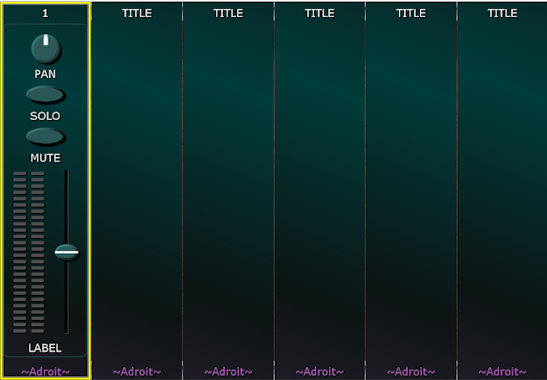
Let’s look at an example of using intelligent cloning to help speed up the creation of a six-channel mixer.
First create a cabinet containing six Custom Panel modules side by side. The quickest way to do this is to add one then use ALT dragging to duplicate it.
Then right-click on the left-most panel and add a mixer strip…
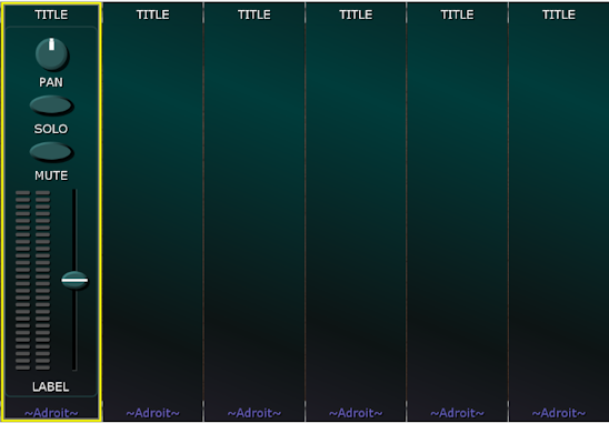
Right-click on the mixer strip and set its VCA pair to the VCA pair you want to use for channel 1, for instance VCA pair A1.

Change the tiitle of the left-most module to 1 by engaging the EDIT TITLES button on the Custom Look module, double-clicking on the title, typing in 1 and then disengaging the EDIT TITLES button,
Now holding down the CTRL (or ⌘) key, click on the left-most panel to select it…
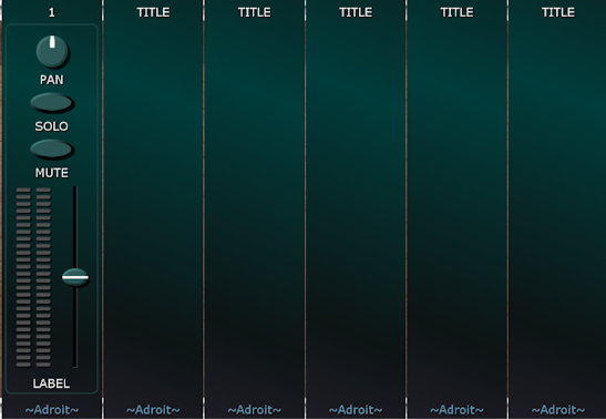
Now while still holding down the CTRL (or ⌘) key, press C to copy the module to the clipboard. Then while still holding down the CTRL (or ⌘) key, click on the module to the right and press V.

Then while still holding down the CTRL (or ⌘) key, click on the next module to the right and press V again. Repeat the click and V press until all six modules have mixer strips then release the CTRL (or ⌘) key.
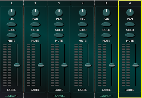
Now each module has the appropriate horizontal and vertical indices to make the background shading (or any subsequent image mapping) work correctly, every other ~Adroit~ logo is suppressed, the titles are labelled 1 to 6 and the mixer strip VCA pair assignments are A1 through A6.
Although this cloning process may seen very laborious at first, with a little practice it becomes easy to do.
When you want to construct something like a complex 16-step sequencer where each step has multiple controls then begin by configuring just one module that’s a “prototype” and clone it 15 times. You might still need to make adjustments to individual modules but the cloning operation can reduce the workload to something that is manageable.