In this tutorial we extend the patch from Tutorial 7 adding simple kick drum, snare, bass, pad and melody parts.
Allow a similar amount of time as needed for Tutorial 7 or slightly longer if you wish to ponder on things.
These two tutorials are the most challenging ones in this series, but once you have completed them you should have a pretty good understanding of the basic principles of LSSP. You will then be able to relax and think about how you might choose to adopt and adapt the technology to your own requirements.
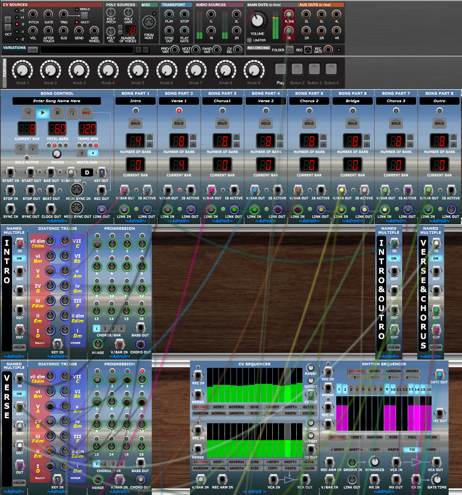
Begin by loading up the patch from Tutorial 7.
As usual engage REPEAT and PLAY on the Song Control module so that you can listen to the changes being made.
Table of Contents
Kick Drum
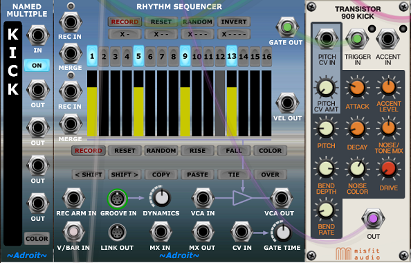
In the cabinet below the Piano add a Named Multiple, a Rhythm Sequencer and a Transistor 909 Kick module.
Double click on the TEXT HERE field of the Named Multiple and type in KICK.
We are going to keep this really simple. You should be able to use the techniques we’ve looked at in earlier tutorials to do something more sophisticated, but for now we’re just going to have a four to the floor kick going all the way through the song.
So all we need for V/Bar sequencing is to patch the global V/BAR OUT of the Song Control module to the V/BAR IN socket of the kick’s Rhythm Sequencer. Then click on its X – – – button to program beats on steps 1, 5, 9 and 13.
Patch the Rhythm Sequencer’s GATE OUT to the 909 Kick module’s TRIGGER IN socket.
Click on the Rhythm Sequencer’s COLOR button to select a color, for instance yellow, to make it easier to find.
Finally patch the OUT socket from the 909 Kick to the 2L(M) input of the Stereo Mixer module so that you can hear the kick drum. Adjust the 909 Kick and mixer module’s controls to taste.
Snare Drum
Rather than use up another cabinet, let’s use the space to the right of the Kick drum sub-patch.
Add a Named Multiple, a Time Split Fills module, two Rhythm Sequencers and a Transistor 808 Snare module.
Double click on the TEXT HERE field of the Named Multiple and type in SNARE.
Link the GATE OUT of the left-hand Rhythm Sequencer to the MERGE input socket of the right-hand one, then patch the GATE OUT of that to the TRIGGER IN of the 808 Snare module.
Patch the OUT socket of the 808 Snare to the 3L(M) input of the Stereo Mixer module.
The Time Split Fills module provides a number of options for creating fills. In this instance we just want an easy way to vary the snare pattern a little so that we get an AAAB sequence that repeats every four bars. So patch the BARS 1-3 output of the Time Split Fills module to the left-hand (A) Rhythm Sequencer and the BAR 4 output to the right-hand (B) Rhythm Sequencer.
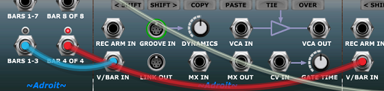
Now connect one of the outputs of the Named Multiple labelled VERSE&CHORUS to the V/BAR IN socket of the Time Split Fills module. This will make the snare play whenever a verse or chorus is playing.
Use the numbered buttons on the Rhythm Sequencers to program patterns something like that shown in the image below…
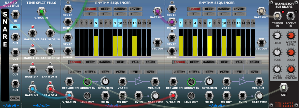
The right-hand pattern can be quickly programmed by clicking on the X – – button and then clicking on button 16 to turn off the final step.
Change the sequencer colors to yellow to match the kick drum just to make the drums a tad easier to find when scrolling up and down.
Adjust the 808 Snare and mixer module’s controls to taste.
Bass
Let’s go for a super lazy bass line that just rhythmically thumps out the chord root in a sparse two bar long pattern.
At the bottom of the patch begin a new cabinet adding a Named Multiple, a Time Split 2, two Rhythm Sequencers, an Oscillator, Filter, Amplifier and Envelope Generator.
Set the Named Multiple’s text to BASS.
As before patch the two Rhythm Sequencers together by connecting the left-hand one’s GATE OUT to the right-hand one’s MERGE socket. Then patch the right-hand sequencer’s GATE OUT to the GATE IN of the Envelope Generator.
Patch the Square Wave output of the Oscillator to the AUDIO IN socket of the Filter and the Low Pass output for the Filter into the INPUT of the Amplifier and one of the OUTPUT sockets of the Amplifier to the 4L(M) input of the Stereo Mixer module.
Feed the positive output of the Envelope Generator to the CV AMOUNT socket of the Amplifier and the FREQ MOD1 input of the Filter. Turn up the FREQ MOD 1 knob to enable the envelope to modulate the Filter’s cutoff frequency.
To make the Oscillator pitch track the bass note of the current chord connect the BASS OUT socket of the last Progression module in the chain (in the cabinet labelled OUTRO) to the PITCH CV socket of the Oscillator.
Set the Oscillator range to a deep 32′ and turn up the PULSE WIDTH knob for a slightly raspy bass sound.
We’re going to have the bass playing all the time like with the kick drum so patch the global V/BAR OUT socket of the Song Control module to the V/BAR IN socket of the Time Split 2 module. And then connect the ODD BARS socket of the Time Split 2 to the left-hand Rhythm Sequencer’s V/BAR IN and the EVEN BARS socket to the right-hand sequencer’s V/BAR IN.
Program a very sparse pattern like the one shown below into the Bass Rhythm Sequencers and adjust the Filter, Envelope Generator and Stereo Mixer until you have a simple bass line that fits in the mix.
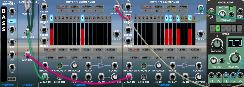
As before change the color scheme, perhaps to red for bass, again to make things easier to find.
Mixer Labels
It’s getting difficult to work out which channel of the Stereo Mixer does what so right-click on the channel numbers and use the Add Label option to label the channels.
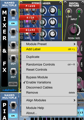
By the way there is nothing special about the channel numbers. Any non-control area of a module will produce the right-click menu when right-clicked. It’s just that the place where the channel numbers are happens to be an ideal position to locate the labels. Also note that labels can be easily repositioned.
Save your work up to this point as a preset called Tutorial 8 just in case something goes wrong.
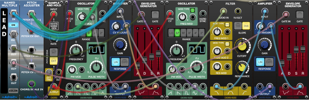
Lead Sound
To carry the melody we could do with a lead sound that’s a little more inspiring than the vanilla synth sounds we have been using in the tutorials so far. So let’s build something that uses modulated FM to create a sound vaguely reminiscent of a distorted rock guitar.
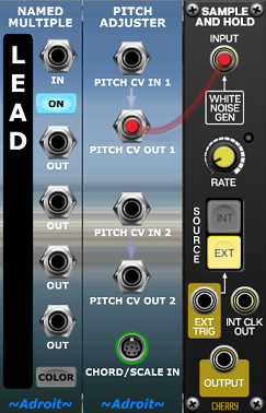
Create a new cabinet at the bottom of the patch and add a Named Multiple. Change its label to LEAD.
We’ll be using CV Sequencers for pitch sequencing which is a fairly crude technique but we’ll make it work by using a Pitch Adjuster to quantize the pitch to use only notes from the current chord. And we’ll be holding the pitch over time by using a Sample and Hold module so that the pitch only changes when a new note starts.
Go ahead and add Pitch Adjuster and Sample and Hold modules to the right of the Named Multiple. Patch the Pitch Adjuster’s PITCH CV OUT 1 socket to the INPUT of the Sample and Hold module.
We’ll be triggering the Sample and Hold from the gate signals output by Rhythm Sequencers rather than its internal clock so click on the EXT button.
Then add an Oscillator, Amplifier, Envelope Generator and another Oscillator to the cabinet. Patch the OUTPUT of the Sample and Hold to the PITCH CV input of both Oscillators. Patch the positive output of the Envelope Generator into the CV AMOUNT socket of the Amplifier.
Set the RANGE of the left-hand Oscillator to 8′ and the right-hand one to 32′.
Click on the MOD TYPE button at the top of the left-hand Oscillator so that it changes from EXP to LN. This is because we want to use linear frequency modulation. Turn up the same Oscillator’s FREQ MOD knob to about 3 o’clock or approximately 65%.
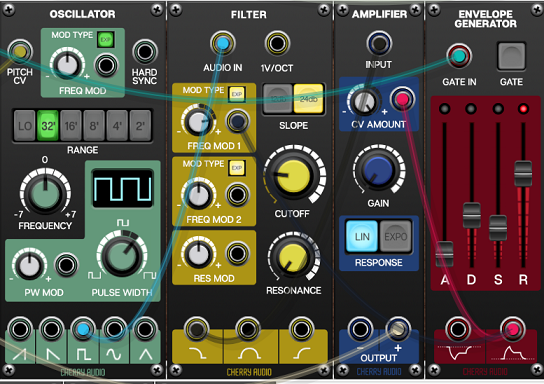
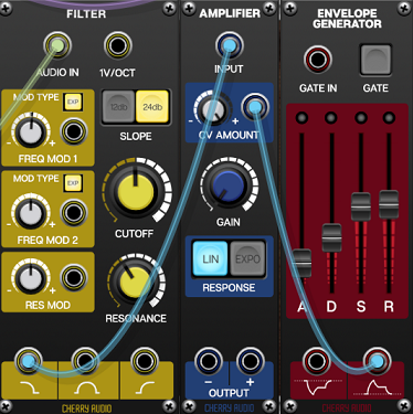
Adjust the Envelope Generator settings as shown in the image below.
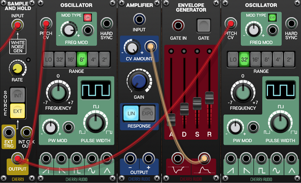
What we want to do is use the right-hand Oscillator (running at audio rate) to modulate the frequency of the left-hand one, but to also modulate the strength of that modulation using the Amplifier and Envelope Generator so that the FM sound changes over the duration of a note.
So patch the Sine Wave output of the right-hand Oscillator to the INPUT of the Amplifier and the + OUTPUT of the Amplifier to the FREQ MOD socket of the left-hand Oscillator module.
This setup produces some pretty complex harmonics so add a Filter so that we can tame the sound with some low-pass filtering and also add a suggestion of amplifier-guitar feedback by using filter resonance.
Patch the Sawtooth output of the left-hand Oscillator into the AUDIO IN socket of the Filter and adjust the CUTOFF and RESONANCE knobs as shown below.
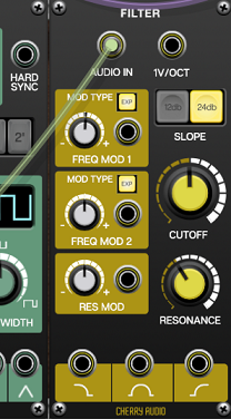
There’s sufficient harmonic change in the modulated FM so we won’t add any filter modulation.
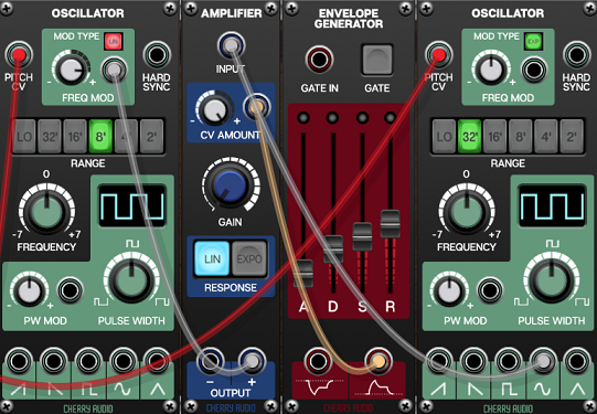
Next add an Amplifier and another Envelope Generator so that we can sculpt the amplitude of the notes. As usual patch the low-pass output of the Filter to the INPUT of the Amplifier and the positive output of the Envelope Generator to the CV AMOUNT of the Amplifier. Adjust the Envelope Generator controls as shown below.
To finish the audio wiring patch the + OUTPUT from the Amplifier into the 5L(M) input of the Stereo Mixer module. And as before right-click on the mixer channel number to add a LEAD label to help identify the channel’s purpose.
You won’t hear anything change of course as we haven’t wired up any sequencing for the lead part yet.
Melody Sequencing I
We are going to have three different sequences for the the Lead sound. One for Verses, one for Choruses and one for the Bridge. Each of these will be just a one bar riff that repeats to keep things simple in this initial demonstration patch. However the actual notes used in these riffs will change over time because they will be quantized to fit the changing chord progressions. So the riffs will automatically morph into musically coherent patterns rather than robotically repeat.
There are huge spaces on the right of the cabinets labelled VERSE, CHORUS and BRIDGE so let’s use this space to hold the melody sequencers.
So on the right side of each of these three cabinets add a CV Sequencer and a Rhythm Sequencer. Leaving a slight gap between the existing Progression modules so that it’s obvious that the melody sequencers are slightly different in function.
Each of the Named Multiples labelled VERSE, CHORUS and BRIDGE already has a V/Bar signal attached to their inputs from the ground work we built in Tutorial 7. So we can use the outputs of the Named Multiples to drive the V/BAR IN sockets of the CV Sequencer and Rhythm Sequencer in each respective cabinet.
Check out the image below. This shows the arrangement in the VERSE cabinet with the V/Bar cable for the CV Sequencer highlighted in yellow.
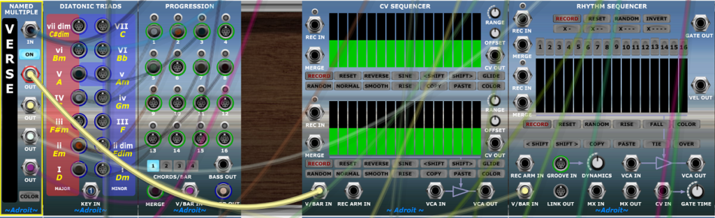
If you look carefully you’ll see another cable from the Named Multiple feeding the same V/Bar signal to the Rhythm Sequencer.
When a verse is playing you should see the familiar highlighted bar moving left to right on both CV and Rhythm Sequencers.
Each of the three cabinets should have virtually the same arrangement. But one for verses, one for choruses and the bottom one for the bridge.
Next we need to make the CV Sequencers control the pitch of the lead instrument / sub-patch. Previously we have been using the MERGE sockets but this was mostly just to keep the wiring a little neater. Here let’s just wire up each CV Sequencer’s CV OUT socket to PITCH CV IN 1 socket of the Pitch Adjuster in the LEAD cabinet.
There are subtle differences between direct parallel wiring like this and using the MERGE facility but it’s not worth worrying about except in exceptional circumstances.
Next we need to complete the melody sequencing wiring by connecting the gate signals from the Rhythm Sequencers to the various gate and trigger destinations in the Lead Instrument. This could require lots of tedious wiring so let’s exploit the facilities of the Named Multiple labelled LEAD to simplify things.
Patch the GATE OUT sockets of all three of the Rhythm Sequencers (in the VERSE, CHORUS and BRIDGE cabinets) to the IN socket of the Named Multiple labelled LEAD. This combines (or merges) all of the gate signals from the Rhythm Sequencers in a similar way to how we just combined the pitch signals of the CV Sequencers.
Now when a gate is high from any of the three Rhythm Sequencers the outputs of the Named Multiple labelled LEAD will go high too.
Now we can finally wire up the three individual modules in the lead sub-patch that require the gate signals.
The multiple mechanism allows a many to one to many geometry that requires less cables than a many to many geometry. This makes it easier to understand what’s going on and easier to make modifications.
So, patch an output signal from the Named Multiple labelled LEAD to the EXT TRIG socket of the Sample and Hold module. This makes the Sample and Hold Module sustain the voltage at its input until it receives another trigger.
Then patch another output signal from the Named Multiple labelled LEAD to the GATE IN socket of the left-hand Envelope Generator in the same Lead cabinet. This drives the frequency modulation modulation envelope for each note.
Finally patch yet another output signal from the Named Multiple labelled LEAD to the GATE IN socket of the right-hand Envelope Generator in the same Lead cabinet. This provides the gate that enables each note’s amplitude to be sculpted as required.
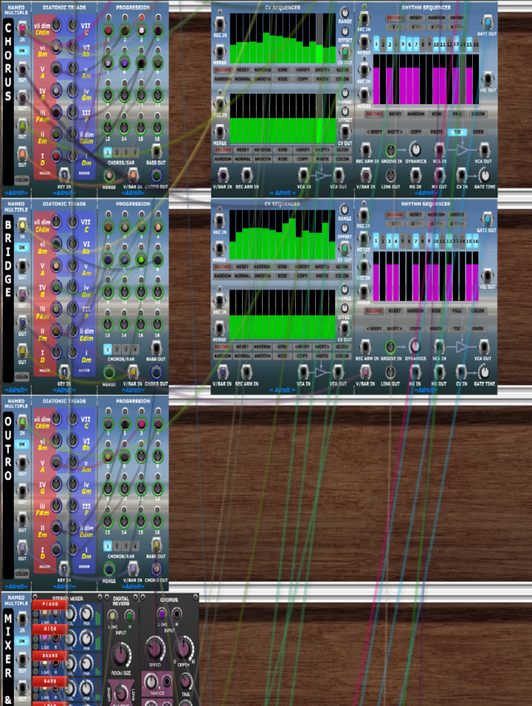
The wiring is beginning to get a bit messy now but the VERSE, CHORUS and BRIDGE cabinets should look like this…
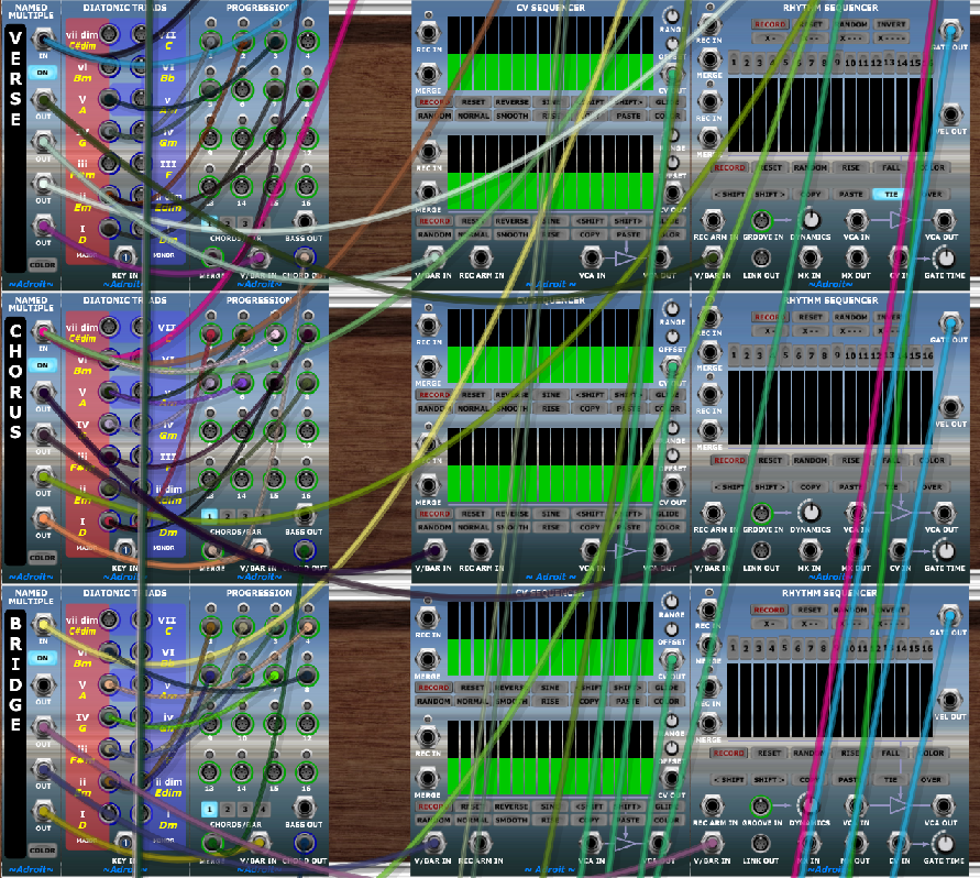
The LEAD cabinet should look something like this…
Getting complex wiring correct requires patience and a methodological approach. Working on large scale patches can be frustrating but the satisfaction when you get it right is immense. If you get totally lost then go back to the last saved version you had that worked correctly and carefully rebuild, testing as you go if possible.
With practice your skills in identifying and solving problems will improve but an incremental approach is always far more effective than trying to create everything in one go.
Melody Sequencing II
OK, we have the wiring of our first complete song finished, hopefully without any mistakes!
You will have the chord progression being played by the piano and a very simple rhythm section made up of kick, snare and repetitive bass.
But still no melody as the six sequencing modules at our disposal are all in their default neutral states and contributing nothing to the sound.
Skip to Melody Sequencing III if you are in a hurry.
As we approach melody programming let’s try to boil it down to three compositional elements – pitch contour, rhythm and contrast.
Pitch contour is that basic up and down thing. Landscape metaphors work well here. Are we talking about rolling meadows, mountain ranges or cliff edges? The frequency, symmetry and size of intervals are important and above all else a good melody is “singable”.
In this first attempt at a song we are using the CV Sequencer to do the task but it’s a bit of a blunt weapon. What we will be doing is programming a broad scope pitch contour that will be sampled by note onsets from a Rhythm Sequencer. It’s a rather hit and miss technique but can produce surprisingly good results if you are prepared to spend a few minutes exploring the possibilities and rejecting the failures until you happen upon something that you think works. It’s pretty useless for transcribing notes that you have already determined though.
Eventually you’ll be able to use Melody Sequencer for much more precise control of pitch sequencing but it’s not ready yet.
Rhythm is something we all feel instinctively. It’s perhaps the most physical aspect of music and of course especially connected to dance. Later we will be able to use the Groove module to tweak the exact micro timing and dynamics of sequences but for now we still have plenty of potential even with just 16 rigid steps.
Contrast is perhaps the most important concept in music. There is nothing worse than a composition with no contrast (unless of course your intension is to create a feeling of monotony) . A melody needs to go on a journey where contrast in pitch contour and rhythm keep a listener enthralled.
Sorry, that’s enough waffle – let’s get down to some practical detail.
The most basic melodic strategy in a verse/chorus/bridge song form is for the verse to have little pitch variation and a fairly slow but interesting rhythm; the chorus to be much more energetic with wide pitch variation and a faster more foot tapping rhythm. The bridge can take one of two routes – either out doing the chorus or dropping down to what is called a break in other genres.
One very important element is the high note. This might occur in either the chorus or bridge.
Another important element is the leap. A change in pitch that is greater than usual. It’s generally a leap upwards but can be downward for a particularly dark effect.
These last two elements are powerful tools in shaping a melody and their timing and harmonic context are important. Having said that happy accidents occur all the time so don’t over think things!
Melody Sequencing III
Ok, everything is wired up and ready to go. Make sure PLAY and LOOP are engaged.
Solo Verse 1.
Program a slow rhythm with TIE engaged into the Rhythm Sequencer in the cabinet labelled VERSE.
In the CV Sequencer in the same VERSE cabinet use the mouse to draw a pitch contour into the upper sequencer with very little up down variation. As described above this is a rather crude technique and the control voltage from the CV Sequencer is being sampled only at the beginning of the new notes programmed in Rhythm Sequencer, so most steps in the CV Sequencer actually have no effect. But after four or five attempts you should happen upon something that works.
I realise this is a very primitive and experimental technique but you will hopefully be pleasantly surprised to discover pitch contours and rhythms that do actually work. As mentioned previously this function will eventually be the job of Melody Sequencer. Sorry to Beta testers if you find this frustrating.
Once you have something that you are reasonably happy with for the verses, click on the SOLO button for Chorus 1. This switches attention to the chorus sequencing so that you can program the sequencers in the cabinet labelled CHORUS.
Perform similar operations as with the verse sequencing but with one or two more notes per bar than the rhythm used for the verses and with greater pitch variation.
Finally SOLO the Bridge.
We’ll go with the idea of the Bridge out doing the Chorus rather than being a breakdown so this time don’t engage the TIE button on the Rhythm Sequencer. This will enable you to program 16th note rhythms and add an extra level of pace to the Bridge.
When programming pitches for the Bridge’s CV Sequencer try to reach a high note or introduce a leap as described earlier. Or have one of these highlights in the Bridge and the other in the Chorus.
Click on the Bridge SOLO button to return to normal play mode.
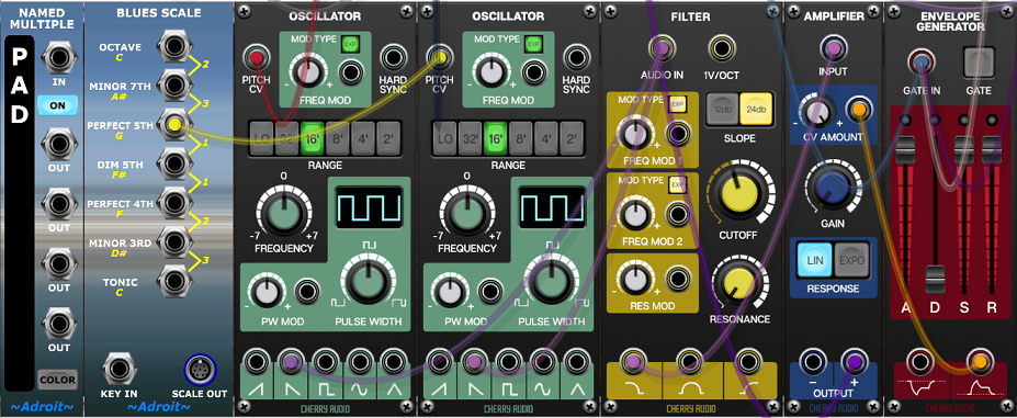
PAD
Let’s add just one last element – a simple pad sound that fades in and out during the Intro and returns to add a bit of a lift to the Bridge and final Chorus.
At the very bottom of the patch add a Named Multiple, Blues Scale, two Oscillators, a Filter, an Amplifier and an Envelope Generator.
Feed both Oscillator PITCH CV sockets with the signal from the BASS OUT socket of the final Progression module. Next patch the PERFECT 5TH socket of the Blues Scale to the right-hand Oscillators PITCH CV socket. This just adds a pitch offset so that the Oscillators play a fifth apart.
Patch a Sawtooth output from each Oscillator to the AUDIO IN socket of the Filter then the Low Pass output of the filter to the INPUT of the Amplifier.
Patch the Envelope Generator’s output to the Amplifier’s CV AMOUNT socket and set the Envelope Attack, Sustain and Release controls to maximum.
Then to make the Envelope Generator fire when we want, connect its GATE IN socket to the IS ACTIVE sockets of the Song Part modules for the Intro, Bridge and Chorus 3.
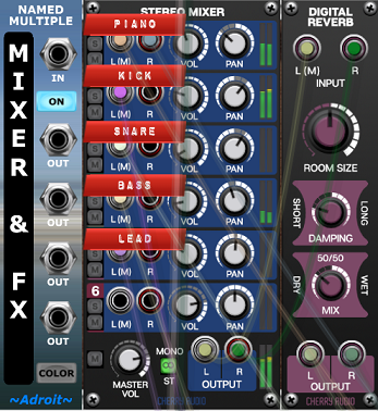
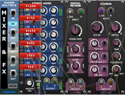
Add a Chorus module to the right of the Digital Reverb module in the MIXER & FX cabinet. Patch the + OUTPUT of the pad’s amplifier to the L(M) INPUT of the Chorus module and patch its L and R OUTPUTs to the inputs of Mixer channel 6. And add a label to the channel with the text PAD.
Finally adjust the Mixer and Filter settings so that the pad sits in the mix properly.
Save your work as a preset called Tutorial 8.
Conclusion
In conclusion you should now have a crude but complete short song with very basic harmony, rhythm and melody. It’s nothing amazing but hopefully you can see how the basic mechanics of LSSP work and can glimpse how you might refine and extend these ideas to create your own far superior compositions.
Note that the addition of extended chords and inversions in the full version of LSSP opens up the harmonic and melodic landscape well beyond the limited scope of basic triads we are using here.
A final note to Beta Testers. If you’ve made it this far I am grateful for your patience.
There are lots of bugs in the current modules and frustrating gaps in functionality. I will be spending coming months trying to solve these problems, making improvements and will eventually be publishing Beta versions of the Melody Sequencer and Groove modules.
I plan to then replace these initial tutorials with improved ones. But I hope they have been of some use in introducing certain aspects of LSSP.
Thanks for your interest, support and very valuable feedback.