The GS Multiplex module was designed to serve as an ideal bridge between the N-Step sequencer and the Granular Synth.

One can interface N-Step directly with the Granular Synth but GS Multiplex offers facilities that enhance the relationship.
The following tutorial assumes that you are already somewhat familiar with both N-Step and the Granular Synth but if you are impatient then you could still download the presets and have a play.
Typically a GS Multiplex module would be positioned immediately to the right of an N-Step Main module as this makes the red, orange, green and blue channel outputs of N-Step align perfectly with the red, orange, green and blue timbral part inputs of GS Multiplex.

Placing all the modules in one cabinet is possible but it’s perhaps best to split the modules across two cabinets.
Table of Contents
A basic patch
Let’s get stuck in and load up a basic patch…
You should hear a simple 16 step monophonic sequence playing. Every step in the gate/trigger pattern is on because the Euclidean DENSITY parameter is set at 100%.
To get an instant feel for the mixing potential try playing with the GS Multiplex parts’ ON buttons shown in the image below.
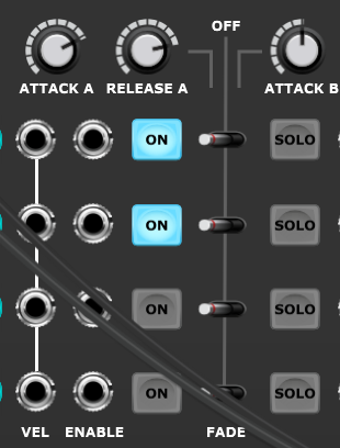
When a button is engaged the associated part fades in and when it’s disengaged the part fades out. Experiment with different combinations while reading on…
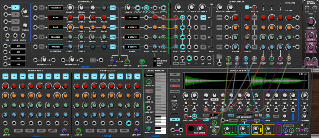
The top cabinet has an N-Step Main module, a GS Multiplex module and the stock Digital Reverb.
The bottom cabinet has two N-Step Aux modules wired to the N-Step Main module to create a 16 step sequencer, a Chord Memory module and a Granular Synth module.
The Chord Memory is programmed with a C Dorian scale and its output is fed to the QUANTIZE input of the N-Step Main module. So all pitches output by the N-Step Main module will automatically belong to the scale.

You could think of Dorian as a slightly happier version of the natural minor scale as its sixth note is a semitone higher.
The wiring between the GS Multiplex module and the Granular Synth looks rather complicated but you’ll discover that you’ll use almost the same setup every time with just the odd variation. Therefore the easiest way to set this up is to retrieve a saved cabinet that already has a GS Multiplex and Granular Synth in it with most of the wiring and control settings already in place.
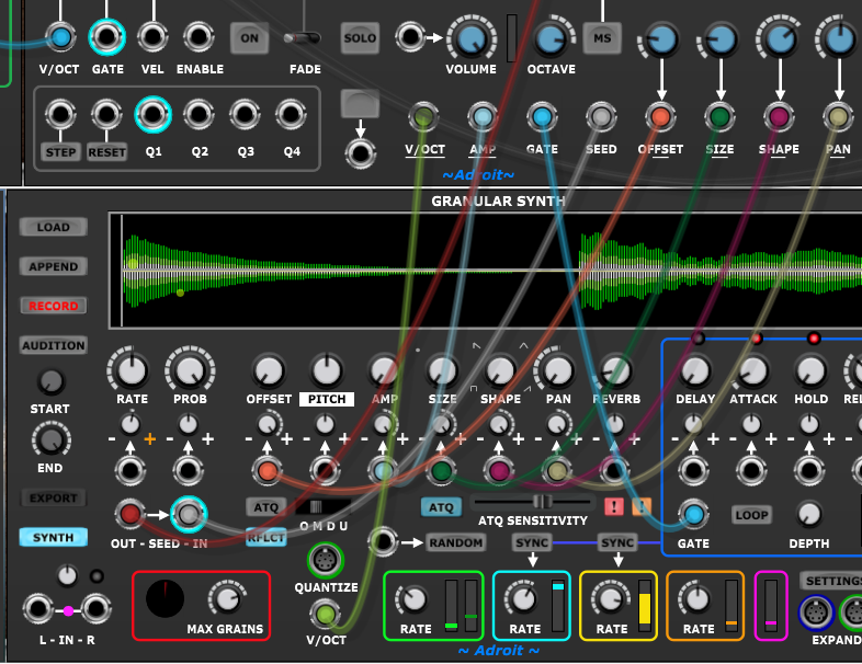
The four connection on the left of the GS Multiplex module are the standard ones described in the GS Multiplex Quick start guide.
To recap:
The GS Multiplex’s V/OCT is connected to the Granular Synth’s V/OCT.
AMP is connected to the Granular Synth’s AMP external CV input.
GATE is connected to the Granular Synth’s GATE.
SEED is connected to the Granular Synth’s SEED IN.
The Granular Synth’s SEED OUT is also connected to the GS Multiplex’s SEED IN.
In addition to the “standard” wiring the P1 through P4 parameter outputs of the GS Multiplex are used to control certain seed parameters of the Granular Synth.
The P1 through P4 labels have been customized (by clicking on the labels and selecting the text to use from the menu) to make things clearer.
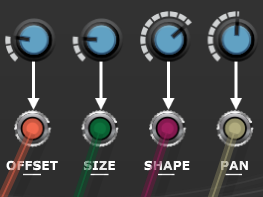
So the P1 knobs control grain offset, P2 knobs control grain size, P3 knobs control grain shape and P4 knobs contol grain pan.
To allow the GS Multiplex to fully control the chosen parameters of the Granular Synth the OFFSET, AMP, SIZE, SHAPE and PAN knobs on the Granular Synth are all turned fully CCW and their attenuvertors are turned fully CW. This maps the 0 V to 5 V CV from the GS Multiplex module to each parameter’s range.
So for instance the P4 knobs set the pan position of each part with 12 o’clock being the center of the stereo image, CCW being left and CW being right.
If you’ve already worked through the main GS Multiplex documentation then this should all be familiar territory.
Automating fades
Rather than manually operating the ON buttons to fade parts in and out let’s see how the logic sequencer sub-module could be used.
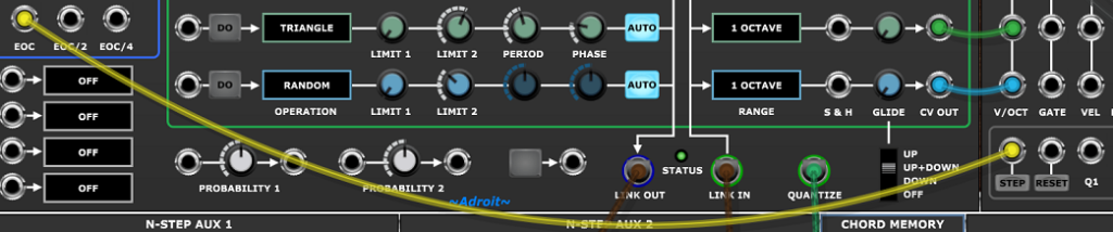
First patch the EOC output from the N-Step Main module to the STEP input of the logic sequencer. This makes the logic sequencer advance one step each time the main sequence reaches its end of cycle.
Then make sure that all the part’s ON buttons are engaged.
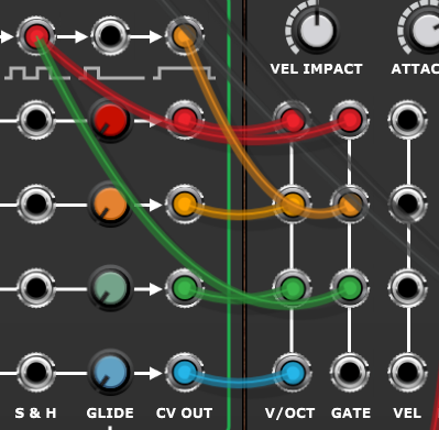
Then patch Q1 to the red part’s ENABLE socket, Q2 to the orange one, Q3 to green one and Q4 to blue one.
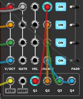
Cable color-coding is recommended when doing this kind of thing even though it’s a bit of a chore selecting the color.
Now you’ll notice that the parts fade in and out in turn. But even though there’s some cross-fading it would sound better with more overlap. We could turn up the ATTACK A and RELEASE A knobs but for more sustained overlap we can add some more cables to create the pattern shown in the table below.
| Red | ON | ON | OFF | OFF |
| Orange | OFF | ON | ON | OFF |
| Green | OFF | OFF | ON | ON |
| Blue | ON | OFF | OFF | ON |
This requires 4 more cables.
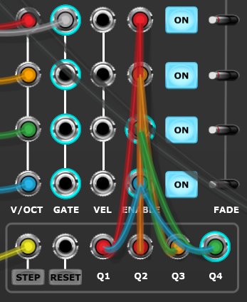
Here’s the patch ready built, if you haven’t been working along…
This sounds better but it still feels a little too busy so let’s slow down the rate of the logic sequencer by connecting its STEP input to the EOC/2 output of the N-Step Main module rather than EOC. This halves the rate of the logic sequencer.
Also let’s say we’ve decided that we want the orange part to stay enabled all the time. There’s no need to add more cables, instead just unplug those feeding the orange part’s ENABLE socket as when nothing is connected to an ENABLE socket the part is enabled by default.
Here’s the modified patch…
Using different gates
So far all steps of the pattern have been on (because the Euclidean operation DENSITY parameter is 100%) and all parts are playing at the same time. So let’s look at introducing some rhythmic interest.
Turn down the DENSITY knob so that 5 steps in the cycle are on.
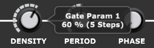
As the PERIOD is 8 and PHASE is 0 this produces the following repeating pattern…

Because all parts are playing the same pattern this sounds rather robotic so let’s begin to add some variety using gate programming.
First patch the far-right gate/trigger output of the N-Step Main module to the GATE input of the orange part of the GS Multiplex module.
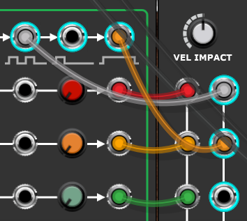
This makes the orange part play at a slightly slower rate – only when a new run of contiguously on steps begins. In this particular patterm this means that steps 6 and 14 are dropped.
However because of the normalled wiring the green and blue parts now use the same gate pattern as the orange part, so they too play at the slower rate.
To make them play as before we need to add a new cable feeding the original gate signal to the green GATE input. Not only will the green part return to the original rhythm but so will the blue part because there is still a normalled connection between the green and blue GATE inputs.
Also because the original gray cable that used to trigger all parts now only controls the red part we’ll change its color to red so that the color-coding is nice and consistent.
Now the red, green and blue parts are playing the same 5 in 8 rhythm while the orange part plays a modified pattern with steps 6 and 14 dropped.
Finally let’s make the blue part play on all 16 steps by feeding its GATE with the left-most gate/trigger output.
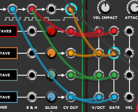
Here’s the finished patch…
Beneath the Ice
Let’s look at another patch.
This sounds quite different to the previous example as it’s using multi-seeding while the previous patch used exclusively one-shot grains. Also this time rather than N-Step controlling pitch it’s controlling the GS Multiplex volume CVs to achieve mix automation.
Click the play button in the top-left of the patch to make it generate a 16 bar piece of dark atmospheric music. There’s a lot of low-end energy so you’ll need to listen with headphones or speakers that have reasonable bass response to hear the sub-bass elements.
It’s using 8 of the free-running sinewave LFOs inside the GS Multiplex to control pitch and pan therefore you’ll get different results each time you run it but the overall structure and feel should remain the same.
In the upper cabinet there’s an N-Step Remote module that looks after starting, stopping and resetting.
The N-Step sequencer is running at a much lower speed than normal – one step per bar at about 50 BPM so an external clock is used. There are a number of options including something as simple as a Mini LFO but this patch uses a Sync Generator and Sync Divider to generate a clock that pulses approximately once every five seconds.
Next there’s a couple of Chord Memory modules and an 8 to 1 Poly Switch. The important element is the scale programmed into the first Chord Memory. The second one and the poly switch are just there to force the quantization to restrict the choice of notes used in the final two bars so that the ending sounds reasonably stable. [In the youtube video a cable was misplaced so this wasn’t actually working. But is fixed in the downloadable patch.]
The scale used is Eb pentatonic minor.

This scale is easy to remember because it’s just all the black notes on the keyboard. It’s the same as a natural minor scale with the second and sixth notes removed, so its formula is 1, b3, 4, 5, b7. It’s also the minor blues scale with the b5 removed so will sound very familiar.
Finally in the upper cabinet there are some effects and a mixer. As the only sound source is a single Granular Synth module and the objective is to create an enormous soundscape the effects need to do some heavy lifting. The feedback for the delay is done externally to the Delay modules so that the output of the left channel feeds the right channel and vice versa. The Chorus is heavily applied to add some air and vibrato most noticeably in the upper registers.
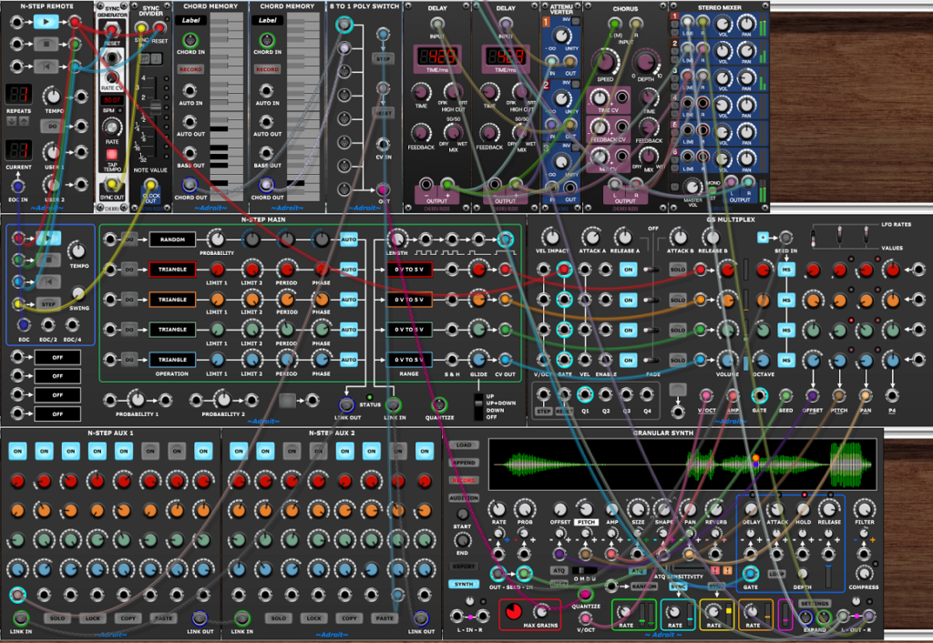
In the middle cabinet we have the N-Step Main and GS Multiplex modules.
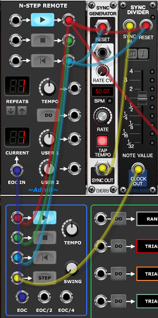
The N-Step Main module’s STEP input is fed a clock from the output of the Sync Generator and its transport is controlled by the N-Step Remote module in the top-left.
The Main module’s EOC output is connected to the Remote’s EOC IN socket. As REPEATS is set to one the sequence plays just once but if you want to listen to the piece repeat then set REPEATS higher using the up arrow button. Each repeat will be slightly different.
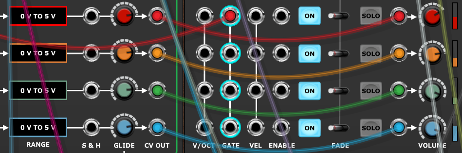
To the right of the N-Step Main module there’s a GS Multiplex module that uses the red, orange, green and blue CV channel outputs from N-Step to control the volume of four drone parts being produced by the Granular Synth below.
The cable feeding the top GATE socket on the GS Multiplex module comes from the Remote’s PLAY output so is high while the sequence plays. Because of the normalled wiring implied by the vertical white line all four parts share the same gate signal.
The cables wired from the CV OUT sockets of the N-Step Main to the VOLUME CV input sockets carry the volume automation CVs. The RANGE settings are all 0 V to 5 V so no quantization is used and all four GLIDE knobs are turned up so that the CVs change gradually rather than abruptly. The VOLUME knobs allow for the overall balance between parts to be adjusted.
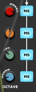
The OCTAVE knobs play an important role here shifting the red part’s pitch up two octaves, the green part down one octave and the blue part down two octaves. The PITCH knob on the Granular Synth is also set at -12 semitones so the basic grain pitches for the green and blue parts before modulation by the LFOs are pretty low. Intentionally so, as the bass sounds are meant to give the whole thing a deep-sea rumble / whale song feel.
All four MS buttons are engaged so all four parts are seeding continuously at the rate set by the Granular Synth’s internal clock.
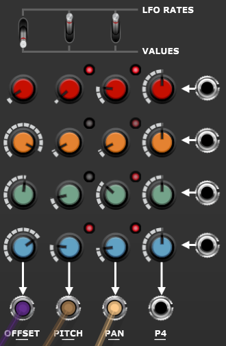
The P1 parameter controls grain OFFSET so the knobs set which part of the buffer grains for each part are seeded from. This gives each part a different timbre.
The P2 and P3 parameters are in LFO RATES mode (as indicated by the switches at the top) so the knobs control the frequency of LFOs rather than absolute values. The four P2 LFOs are being used to modulate grain pitch and the four P3 LFOs modulate grain pan position.
If you hover the mouse over the P2/PITCH knobs you’ll see that the frequency range of the LFOs controlling pitch varies from 0.01 Hz to 0.06 Hz so one cycle every 100 seconds to about one cycle every 16 seconds. So the pitch modulation is pretty slow. As the entire duration of the sequence is only about 80 seconds, parts fade in and out and pitches are quantized to snap to the scale, it’s not obvious to the listener that the underlying pattern of change is actually relatively simple.
The bottom cabinet contains two N-Step Aux modules where each step represents one bar. The 64 knobs control the volume level of each of four parts across the 16 bars. Their initial values were set by experimentation using N-Step TRIANGLE operations with various periods and phases and then they were tweaked while listening to the results. As the much of the musical outcome varies depending on the ratios of the P2/PITCH LFO rates this tweaking took a fairly long time as the effects are more statistical than predictable. But as the results constantly evolve it was quite a pleasant job – slowly adjusting levels until the broad outline of flow felt right.
Next to the Aux modules we have the Granular Synth, the module that’s doing all the sound generation.
The buffer contains four different samples that were joined together using the APPEND function. This is a very useful technique for expanding the sonic range of a single Granular Synth as simply by using different offsets, different grains can have quite distinct timbres.
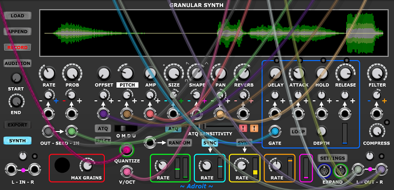
As you can see from the image above there’s a lot going on here so we’ll work through the connections and settings from left to right (which is also roughly how the signal path maps to the module’s panel).
The RATE knob’s base setting is about 9 grains per second but positive modulation is being added to this so that most of the time the seeding rate is in the low audio range. The modulation is coming from the Granular Synth’s envelope generator as can be seen by the attenuvertor’s + sign being blue, the color-code for the envelope generator.
The GATE for the envelope generator is coming from the N-Step sequencer’s fourth gate/trigger output so is high whenever the current step is on according to the ON buttons of the Aux modules.

The ATTACK rate is fast but the RELEASE rate is over 5 seconds so when the gate drops the seeding rate slowly drops from very high to the base rate of about 9 times a second. This adds a bit of rhythmic interest now and then.
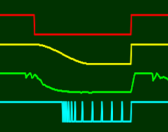
In the long timebase CV Watcher image above the red trace shows one episode of the gate dropping and the yellow trace shows the impact on the envelope. The green trace shows the grain density and the cyan trace shows the seeding clock slowing down. The cyan trace isn’t accurately capturing the high seeding clock rate though, instead it just appears to be high because of an imaging artifact.
The PROB knob is set at 100% but there’s some negative probability modulation from grain DENSITY (note the color-coded red minus sign) so as the number of grains gets higher more and more seeder clocks are dropped. This introduces some instability to the seeding which results is some nice organic dirt being added to the sound when it gets busy. Importantly it also acts as a negative feedback loop that limits the number of grains being produced as the 150 simultaneous grains limit set by the MAX GRAINS knob is approached.
Beneath the RATE and PROB controls the SEED OUT socket provides the seeder clock for the GS Multiplex module and gets the modified (due to multiplexing) clock back via the SEED IN socket.
The OFFSET, AMP and PAN knobs are all fully CCW and the associated attenuverters are fully CW. As discussed in the GS Multiplex documentation this maps 0 V to 5 V onto these parameters’ entire range.
ATQ and RFLCT are both disengaged as they are not useful in this patch.
The PITCH knob is set to -12 semitones, dropping the base pitch of the buffer sample by an octave. The attenuvertor was set by ear in order to limit the modulation range to something that gave a wide range but wasn’t too excessive.
The OMDU switch is set to monophonic mode so that arpeggiation is switched off and quantization is on.
The QUANTIZE socket is fed from the output of the Poly Switch in the upper cabinet. For most of the time this is the S-Poly signal containing the penatonic minor scale but for the last two bars switches to just the Eb root note. This is an attempt to avoid the pitch wandering about near the end of the piece but could be improved. One idea would be to add another stage and force a cadence to give a stronger feeling of completion.
SIZE is set so that grains are on average quite long, then there’s some size modulation from LFO1 which is set to a sedate 0.08 Hz.
SHAPE is set so that grains have on average a triangular shape, but again this is modulated. This time by LFO2 which is set to 0.07 Hz. To add a little more interest LFO2’s SYNC button is enaged so it resets when the envelope attack phase starts.
REVERB is set high to diffuse the sound and add more space. There’s also some modulation using Grain Pitch so different pitched notes have different amounts of reverb.
The FILTER cutoff is set so high that most of the signal passes unchanged through the filters but there’s a small amount of brownian modulation from LFO4 that makes the very high frequency content fade in and out a little.
The idea with these modulations is to add some slow, complex but subtle motion to the sound. The last thing we want in this application is anything robotic.
Finally the COMPRESS knob is set fully CW so there’s 16:1 compression applied to the outputs. This is because the Granular Synth is sometimes pumping out 150 loud grains and at others just a handful of quiet ones. The dynamic range is so large that without compression you’d have to turn the volume down so much to avoid distortion that the quiet sections would then be too quiet.