
This page introduces the Granular Synth and serves as a comprehensive reference manual. The Granular Synth Operation page is also highly recommended and includes a number of downloadable presets.
The GS MIDI X and GS Multiplex pages cover these two important expansion modules in detail.
Table of Contents
Introduction
The main module is a granular synthesizer that works on either pre-recorded audio files or input captured using an integrated recording facility.
WAV, MP3, AIFF and OGG file formats are supported so you can load up just about any sample you can lay your hands on.
A major component of the module is a buffer that holds a segment of audio. A waveform display shows a view of this buffer along with other information.
The waveform display shows a mono representation of the buffer content but the Granular Synth is otherwise fully stereo capable.
A grain is a (generally quite brief) sample of sound extracted from somewhere in the buffer. Individual grains can be manipulated in various ways – they might be shifted in pitch, have their level adjusted, optionally be played backwards, have an envelope shape applied, be assigned different stereo positions and amounts of reverb.

Many different grains may be layered on top of each other to create a complex texture called a cloud.
Clouds consisting of up to 500 simultaneous grains can be supported providing sufficient CPU power is available.
The generation of a grain is called seeding and this can be done at a regular rate, pseudo randomly or on receipt of an external trigger. Seeding rates can vary from perhaps just once or twice a second all the way up to audio-rates.
At a higher level of organization an envelope contour can be applied to the entire grain cloud. Filtering and compression are also built-in.
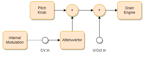
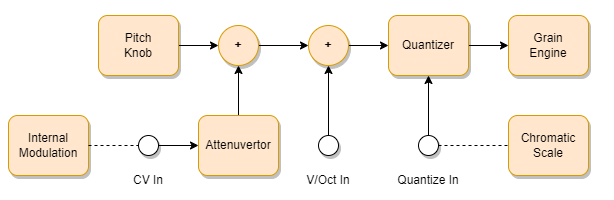
Regular one volt per octave control of pitch shifting is available along with quantization to scales and chords. In addition novel grain pitch sequencing features allow clouds to be easily organized to form granular chords.
The Granular Synth also features something called ATQ (Automatic Transient Quantization) that enables you to automatically slice a rhythmical sample into pieces and reassemble it in new ways.
An important aspect of granular synthesis is the modulation of the various parameters. Internal random and periodic modulation is available but each parameter can also be individually controlled by an external CV signal.
Note that the parameters for a grain are sampled at the instance that it is seeded and remain fixed during its lifetime. So for example if the pitch parameter is being swept up and down then rather than the pitch of all active grains changing in tandem each grain keeps the pitch shift setting that was current at the point of its creation – producing a polyphonic arpeggio effect rather than a unison siren.

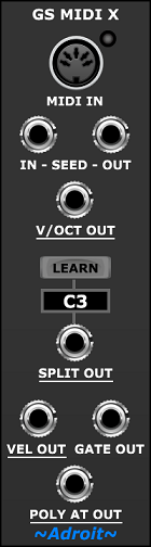
A compact but powerful module called GS MIDI X is included in the Granular Synth bundle. It enables the Granular Synth to be played more like a conventional MIDI instrument. As well as adding multi-voice capabilities it supports polyphonic aftertouch and keyboard splits.
Another powerful expansion module that’s included in the Granular Synth bundle is GS Multiplex.
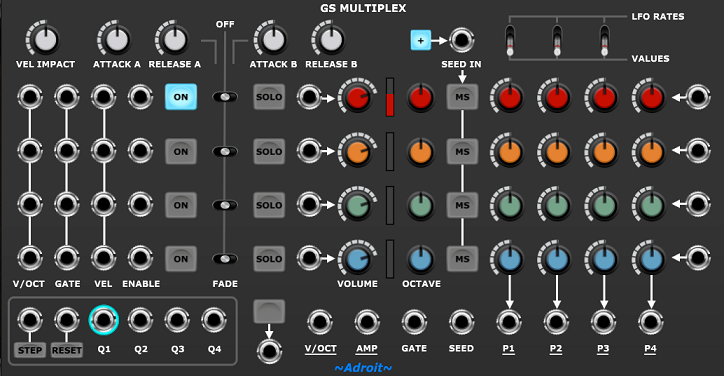
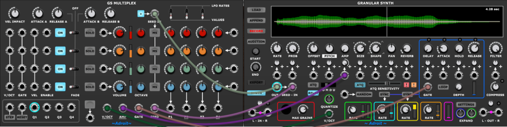
This effectively transforms the Granular Synth into four semi-independent monosynths. It’s great for multi-timbral work and is especially useful when using the Granular Synth in conjunction with the Adroit N-Step Sequencer.
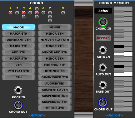
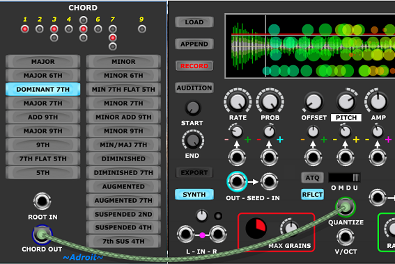
The Granular Synth offloads pitch quantization to external modules by using something called an S-Poly connection. This reduces the size of the module and opens up a range of options. Two modules from the Adroit LSSP system (Chord and Chord Memory) that produce these S-Poly signals are included in the Granular Synth bundle. These enable you to select a wide range of preconfigured chords or program your own chords and scales using either virtual or physical keyboard input.
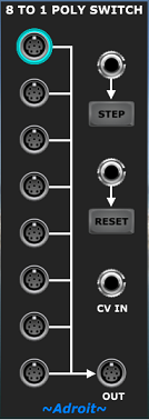
Another module borrowed from LSSP is the 8 to 1 Poly Switch. This enable you to switch between chord signals effectively enabling you to sequence chord progressions.
An optional add-on module called the Granular Synth Breakout is available. Ths extends functionality in several areas, for instance allowing greater control over how the Granular Synth’s RANDOM button works and providing access to the Granular Synth’s internal modulation sources so that you can use them to modulate parameters in other modules. Please note that the Breakout is not included as part of the Granular Synth bundle.

Quick Start Guide
Load the Granular Synth module into a new empty Voltage Modular patch.
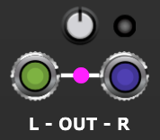
Connect the module’s outputs to Voltage Modular’s MAIN OUTS by patching the Granular Synth’s L OUT socket to the 1L(M) socket and the R OUT socket to the 1R socket.
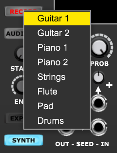
Click on the Granular Synth’s RECORD button. As nothing is currently connected to the module’s inputs a menu pops up that enables you to select one of several built-in test samples.
Select one of the samples from the menu. The module will then automatically switch to Synthesizer mode (as indicated by a green waveform display) and you should hear a very basic granular sound with grains being seeded halfway through the buffer. You should also see a small flashing circle on the waveform display.
Each grain is represented by a circle superimposed on the waveform display. The circle’s diameter represents the grain’s amplitude. The horizontal position indicates where in the buffer the grain’s audio is being extracted from.
Now click on the RANDOM button. Each click randomizes the grain parameters and after a few clicks you should hopefully find something interesting.

Slowly turn the RATE knob up and down. You’ll see and hear the seeding rate vary from very fast to very slow.

Experiment with different settings of the OMDU switch to select between various pitch quantization and arpeggio options.

M = Mono
D = Down
U = Up
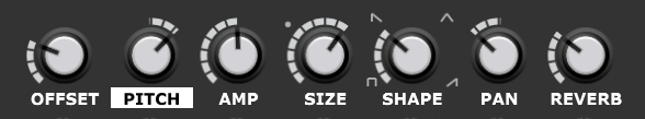
Try using the mouse on the waveform display. This enables you to adjust the OFFSET control and one other parameter at the same time. The default for this second parameter is pitch (as indicated by the highlighted PITCH label) but you can left click on any of the other parameters’ labels (except OFFSET) to select them.
The vertical position of a grain’s circle shows the grain’s value for the selected parameter.
Each of the Granular Synth’s 14 parameters has a main control knob and its own attenuvertor and CV input socket.

When no external CV source is connected you can click on the + or – symbols of a parameter’s attenuvertor to select an internal modulation source.
Color coding of the + and – symbols is used to indicate which modulation source is assigned.
A right click on the label beneath any of the main knobs randomizes the knob’s setting, the associated attenuvertor and the choice of internal modulation sources. This is a very convenient way to explore how each parameter affects the sound produced by the module.

When playing with the Granular Synth module in isolation (like in this Quick Start Guide) it’s good to understand how the Envelope Generator might impact things as we want to hear sounds even though nothing is attached to the Envelope Generator’s GATE input.

When nothing is connected to the GATE socket then the Granular Synth behaves as if an always high gate signal is being applied. This is indicated by the ring surrounding the socket being illuminated.
When the LOOP button is engaged (which it is by default) the Envelope Generator retriggers at the end of its cycle – effectively becoming an LFO. This is very useful as the Envelope Generator output can be used to modulate all kinds of parameters and the exact shape of this modulation can be controlled by altering the DELAY, ATTACK, HOLD and RELEASE parameters.
The DEPTH knob controls the impact that the Envelope Generator has on the overall amplitude (volume) of the cloud. By default the DEPTH knob is set fully CCW (counter clockwise – the minimum setting) and the Envelope Generator has no impact, so sound passes straight through.

When the DEPTH knob is set fully CW (clockwise – the maximum setting) the Envelope Generator operates like a conventional synthesizer’s VCA envelope.
Intermediate DEPTH settings allow the Envelope Generator to adjust the amplitude but some audio still passes through even when the envelope value is zero.
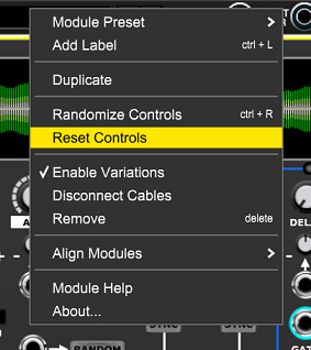
To reset all the knobs and buttons to their default setting right click on the title or a blank part of the module and select Reset Controls from the menu.
First Encounter
The video below shows what your first ten minutes of experimenting with the Granular Synth might be like if you follow the Quick Start Guide above. It’s not meant to be a polished demo nor is it intended to show off all of the features.
The First Encounter video uses an earlier version of the Granular Synth so is slightly out of date but still gives you a good idea of what to expect when first experimenting with the module.
Second Encounter
The video below shows the kind of thing that you might be able to do after a few days.
Documentation
We’ve only just scratched the surface of the Granular Synth. It’s a deep module with much subtle complexity. However it’s been designed to be as easy to use as possible and experimentation will take you a long way. When curiosity finally gets the better of your intuition you can refer to the comprehensive reference documentation further down this page. In addition the following resources are available…
Granular Synth Operation, GS MIDI X, GS Multiplex, Chord, Chord Memory, 8 to 1 Poly Switch and GS Breakout.
The first three of these contain a number of downloadable presets.
While inside Voltage Modular you can access this webpage by selecting Module Help from the Granular Synth’s right click menu (providing you are online).
Mono-Synth Setup
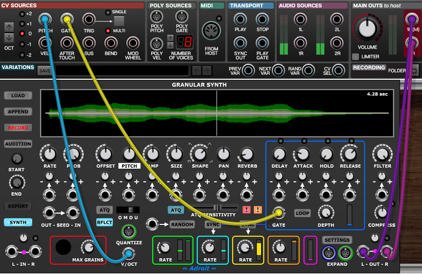
The Granular Synth’s forté is experimental sound production but naturally one will often want to use it as a conventional voice. There are several approaches to this. The most straightforward is to treat it as a regular mono-synth. Simply feed a standard one volt per octave pitch control voltage to the V/OCT socket, a standard gate signal to the GATE socket, disengage the LOOP button and set DEPTH to maximum.
The image below shows a very basic setup for keyboard control. In practice you might want to use velocity, aftertouch and mod wheel CVs to control parameters too, but this is just a matter of adding a few patch leads and adjusting each parameter’s attenuvertor.
You’ll want to tweak various controls as the initial settings are pretty dull just like any INIT patch. The choice of sample is obviously crucial but then you might want to increase the SIZE setting so that grains overlap and experiment with the OMDU switch. Try right clicking on the main control labels (for instance RATE, OFFSET, PITCH and FILTER) to randomize particular parameters and their modulation.
Connecting the PITCH output from Voltage Modular’s I/O Panel to the V/OCT input adjusts the pitch of the Granular Synth to track the note played on your MIDI keyboard. But the exact pitch you end up with depends on the inherent pitch of the sample, the setting of the PITCH knob, any pitch modulation if the pitch attenuvertor isn’t at 12 o’clock and also the setting of the OMDU switch.
With default settings and a sample tuned to C you’ll end up with the simple relationship between the note played on the keyboard and the notes you hear. Because the default setting of the OMDU switch is D (down), you will hear a descending arpeggio. Because nothing is connected to the QUANTIZE input socket the arpeggio will default to a minor 9th chord. So if you play C you’ll hear a D-Bb-G-Eb-C arpeggio.
To disable the arpeggiator change the OMDU switch to O (off) or M (monophonic) you’ll then hear a repeated C if you play C.
Paraphonic Setup
Because the Granular Synth has some neat pitch control facilities and can produce a very large number of simultaneous grains it’s possible to use it as a paraphonic synthesizer in order to play chords. There are two basic approaches to this, one using arpeggiation which will be discussed first and a more sophisticated technique called time-division multiplexing that uses the services of either GS MIDI X or GS Multiplex.
The basic patch below shows how to use the Chord Memory module in record mode to play chords using the arpeggiation approach.
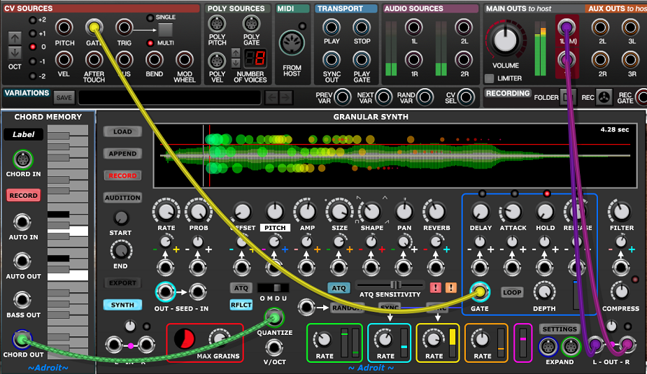
Note there are some limitations as Chord Memory isn’t really designed for live playing so you will need to practice a little to achieve useful results using a MIDI keyboard.
How this all works is that when a Chord Memory module’s RECORD button is engaged while nothing is plugged into the CHORD IN socket, it examines whatever musical data is being fed to Voltage Modular (either from a MIDI keyboard or from a DAW) and remembers it. As long as a note is held it will keep remembering new notes as it’s designed to store things like scales as well as chords. So to change to a new chord you need to remove all your fingers from the keyboard before playing the next chord. In other words legato playing will mess things up.
The CHORD OUT S-Poly signal from the Chord Memory module is then fed to the QUANTIZE input socket of the Granular Synth. Then so long as the Granular Synth OMDU switch is in Up or Down mode you’ll end up with an arpeggio playing the notes of the chord. Providing that the RATE and SIZE parameters are set high enough you will hear a granular chord because the grains will overlap.
It’s not a super elegant setup but you should find that it can produce some stunning results and with practice you might find some novel keyboard tricks that enable you to do things that aren’t normally possible on a keyboard – like massive sustained chords that use more notes than you have fingers or voicings that two hands can’t span.
You’ll probably need to set the MAX GRAINS control to maximum to hear chords that contain more than ten notes.
GS MIDI X
A recent addition to the Granular Synth bundle is the GS MIDI X module. It was designed with keyboard players in mind and therefore enables a far more natural playing style than using Chord Memory. It also supports keyboard splits and polyphonic aftertouch.
A detailed description of this expansion module along with several presets is available here.

GS Multiplex
Another expansion module included in the Granular Synth bundle is the GS Multiplex. This effectively turns the Granular Synth into four semi-independent monosynths. It was mainly designed as a bridge between the N-Step sequencer and the Granular Synth but has other applications such as the creation of complex layered sounds – think four Granular Synths playing at once.
A detailed description of this new module along with several presets is available here.
Basic Operations
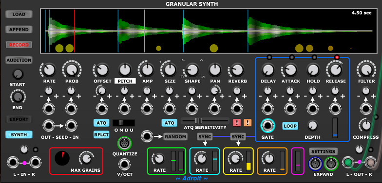
A number of buttons on the left side of the module allow key tasks to be carried out with ease.
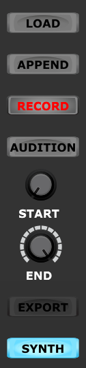
LOAD
Loads the buffer with a sample from a file. Alternatively a sample may be loaded by dragging and dropping a file on to the module.
WAV, MP3, AIFF and OGG file formats are supported. Sample files may be mono or stereo.
If the buffer contains a mono sample this doesn’t mean that the module’s output will be restricted to mono as individual grains have their own stereo positions. However you will get a richer stereo image when working with a stereo sample as panning then shifts the balance of the stereo grain rather than just positioning a mono grain somewhere in the stereo field.
The Load button is disabled when the module is in Record mode.
APPEND
Loads a sample from a file and appends it to the existing buffer content. This enables you to collect together a number of separate samples in a single buffer. This can be a very useful for expanding the sonic range of a single module without it having any impact on CPU use.
The Append button is disabled when the module is in Record mode.
RECORD
Records audio from the input sockets directly into the buffer. The buffer expands automatically as required – the buffer capacity increasing by two seconds every two seconds.
If the Record button is clicked while nothing is connected to the input sockets then a pop-up menu enables you to select one of the built-in test samples. This is useful for initial experimentation.
In record mode the waveform display is colored red.
If only one input is connected then you will end up with a mono recording. But this doesn’t mean that the ouput will be restricted to mono as each grain has its own stereo position.
Recording can be ended by clicking on the Record button again or by clicking on the Audition or Synth buttons. Recording will also end automatically if the total recording time exceeds 60 seconds.
Samples longer than 60 seconds can be still be loaded from files but in practice you’ll find that 60 seconds is more than adequate when recording something live and will usually even allow enough time for you to record two or three takes. You can then use the Audition trim facility described below to select the take you like best.
While recording the input signals are fed directly to the outputs to simplify monitoring.
When any inputs are connected the module’s Envelope Follower responds to the input signals so the magenta colored meter gives a rough guide to input level when recording.

Although the module itself won’t clip when overdriven the file copy of the sample can so care needs to be taken when recording.
The small knob above the input sockets allows input gain to be adjusted. The LED next to it indicates clipping. If it illuminates turn the knob CCW (counterclockwise) slightly until the LED no longer flashes.
A soft limiter kicks in at very high levels to help tame things, but don’t rely on this as limiting causes signal coloration and fast transients can still cause clipping anyway.
AUDITION
Plays the untreated buffer content in a loop and optionally allows for a subsection of the buffer to be non-destructively selected using the START and END trim knobs.
You can also use the mouse to adjust the trim by clicking and dragging on the waveform display.
In Audition mode the waveform display is colored blue and always shows the entire buffer. Any inaudible areas are marked with a grey background.

To make fine adjustments to trim hold down the CTRL (or ⌘) key while adjusting the knobs.
Tip: if you are trying to extract a subsection that is tiny compared to the overall buffer size then first make a slightly over-generous approximation and export it then load that file back in to do a more precise trim.
If the START trim setting is set later than the END trim setting then the subsection will play backwards and will be marked with a pink background.
Trim can only be adjusted while in Audition mode.
EXPORT
Saves the buffer (or a subsection of the buffer if trimmed using the Audition trim knobs) as a WAV file.
EXPORT only works when in Audition mode.
When exporting a stereo sample the option of converting it to mono is offered. Most of the time you’ll want to save as stereo but it can be useful to convert to mono sometimes. For instance if you are wanting to reduce preset file sizes when collaborating with someone via a poor internet connection or if you want to squeeze a little more performance out of an old machine (the Granular Synth can process mono samples slightly more efficiently than stereo ones).
The combined funtionality of Load, Append, Record, Audition, Trim and Export enables you to perform all basic audio editing operations using just the Granular Synth.
SYNTH
This is the Granular Synth’s main mode of operation. It allows grains and notes to be generated using the content of the buffer (or a subsection of the buffer if trimmed using the Audition trim knobs).
If Audition trim has been applied then the waveform display shows a zoomed in view of just the trimmed subsection. From the perspective of the granular synthesizer the audio outside of the trimmed subsection does not exist.
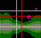
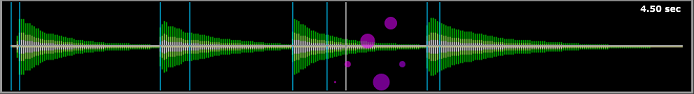
The Waveform Display
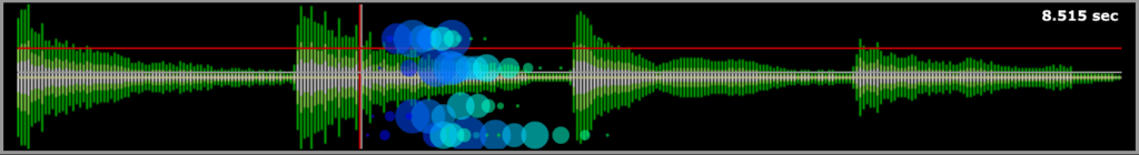
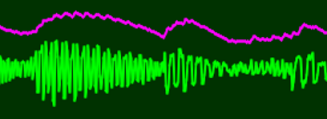
The waveform display gives you a lot of visual feedback about what the module is doing. The most obvious feature is the representation of the buffer content. In Record mode the waveform is red, in Audition mode it’s blue, in Synth mode it is green.
Grains are represented by colored circles. Their horizontal position shows where a grain is in the buffer. The diameter represents the amplitude of a grain.
One way to imagine what’s going on is to think of the waveform display as a piece of magnetic recording tape, while each circle represents a playback head flying along the tape picking up signals.
Each new grain has a slightly different color to the last, cycling through the color spectrum. This gives you a way of judging seeding rate, cloud density and how old individual grains are.
The vertical position of a grain depends on which grain parameter you want to look at. This can be changed by left clicking on the label beneath the main knob of a grain parameter. So for instance if you click on PAN then grains that are on the right of the stereo image are shown higher up the display than those on the left.
Note that when PITCH is selected the octave part of the pitch is ignored by the display (so for instance an F# will always appear at a particular vertical position regardless of which octave it’s in). Also OFFSET can’t be selected as this information is already being displayed by horizontal position.
If you have an old computer with little in the way of graphics acceleration you will probably need to uncheck the Display All Grains option in SETTINGS to reduce CPU load. Even with a powerful machine you may wish to do this sometimes just to optimize a patch, especially if you have multiple copies of the Granular Synth running at the same time.
With the Display All Grains option unchecked there will still be a single grain displayed. This gives you just enough information to work out roughly what’s going on.
The vertical white line shows the position in the buffer as set by the OFFSET knob. The fainter vertical red line shows how this position is being modified by modulation.
The horizontal white line shows the setting of the currently selected parameter. The fainter horizontal red line shows how this parameter is being modified by modulation.
These lines are called the Base and Final Crosshairs and you can switch them off in the SETTINGS if you desire.
You can click on the waveform display and drag the base crosshairs about with the mouse. This enables you to easily tweak two knobs simultaneously.
Incidentally the MOUSE GATE socket on the Granular Synth Breakout module provides a signal that is high when the left mouse button is pressed and the mouse cursor is over the waveform display – this can be useful in performance situations.
Note that non-grain parameters (for instance RATE or PROB) aren’t reflected in the vertical position of the grain circles as they are global settings rather than specific to an individual grain, but they can still be selected. That’s why sometimes you will see a label with a solid highlight (representing a grain parameter) or an outline highlight (representing a non-grain parameter).

It’s possible to view both a grain parameter (by vertical position of a grain’s circle) and a non-grain parameter (by vertical position of the white and red horizontal lines) at the same time.
Seeding Parameters
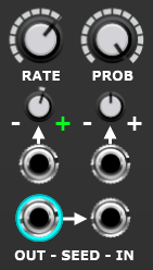
RATE
This parameter controls the rate of an internal clock that triggers grain seeding. Each tick of this clock usually generates a grain although whether a grain is actually seeded also depends on the probability parameter.
The basic range of the internal clock frequency is eight octaves when there’s no modulation applied. So when the RATE knob is fully CCW the seeding rate is C-4 (approximately once per second). When the knob is fully CW it’s at audio rate C4 (middle C). At the maximum setting grains are generated 261.626 times per second. Obviously seeding so many grains per second puts considerable strain on your CPU but it can produce some very interesting sounds.
The knob’s tooltip displays the rate in grains per second. Remember this number is the base rate without any modulation. To set exact values right click on the knob and select Edit Value. As a convenience you can enter C0, C1, C2, C3 or C4 as well as numerical values in Hz.
Note that internal or external modulation can be used to extend the seeding rate beyond the range of the RATE knob.
The internal clock’s rate can be voltage controlled by an external modulation source if required. When the attenuvertor is set fully CW then this modulation operates at exactly one volt per octave. So in this situation it’s possible to treat the seeding clock as an audio VCO to explore advanced forms of granular modulation. The Edit Value short cuts help here as you can type in say C2 to set the base value to match A440 tuning. Alternatively you can bypass the seeder altogether and plug the output of an external VCO module into the Granular Synth’s SEED IN socket.
Audio-rate seeding is a powerful technique for creating very dense textures but sometimes it can produce a ring-modulation like effect, however simply adding a small amount of modulation to one or more parameters generally transforms the effect into something more pleasant sounding.
When exploring audio-rate seeding remember that the intrinsic pitch of the sample, the pitch shifting applied and the rate of seeding all interact.
If nothing is connected to the CV input socket then the small attenuvertor knob is repurposed for internal modulation as described shortly.
The SEED OUT socket provides a signal that triggers every time the internal clock and probability mechanism fires.
An external clock plugged into the SEED IN socket will bypass the internal clock. One use for this facility is to implement tempo synced seeding.
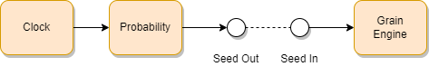
When using multiple Granular Synth modules in a patch it can sometimes be useful to connect the SEED OUT socket of one “master” to the the SEED IN sockets of any “slaves”. All of the modules will then seed grains at the same time (or you could insert clock dividers to generate interesting rhythms).
When something is plugged into the SEED IN socket the internal clock no longer impacts the Granular Synth but it’s output is still available for other uses via the SEED OUT socket.
In certain circumstances the internal clock is reset when the module’s GATE socket detects a rising edge. This allows a grain to be seeded exactly in sync with the beginning of a note event. See the discussion of the envelope generator below for more detail.
PROB
This parameter controls the probability of a grain actually being seeded by the internal clock described above.
When no modulation is applied then the main knob stops grains being produced when fully CCW. When fully CW grains become 100% certain. 12 o’clock produces grains with 50%. probability The knob’s default setting is fully CW.
If a signal is connected to the CV input then it modulates the probability according to the setting of the small attenuvertor knob. One application of this is to produce gated seeding – for instance one might want grains to only be created when a key is held down.
If nothing is connected to the CV input socket then the small attenuvertor knob is repurposed for internal modulation as described shortly.
Max Grains

The MAX GRAINS knob controls how many grains can be active at the same time. It can be set to anything between 3 and 500 grains. The default setting is 150.
The pie chart on the left of the knob indicates how many grains are currently active as a proportion of the knob’s setting.
The CPU load required to deliver hundreds of simultaneous grains is very significant so the MAX GRAINS knob is useful for adjusting CPU usage when running the Granular Synth on older machines (although with low settings the clouds produced will obviously be far less dense than on high settings).
The knob setting can also be used creatively as it changes how the Density modulation parameter is calculated.
Attenuvertor Operation
Below each of the main parameter knobs there’s a smaller knob and a CV input socket.
When the socket is connected to an external CV source then the small knob controls the amount of modulation applied to the parameter.
When the smaller knob is at its default 12 o’clock setting there is no modulation. As the knob is moved CW then the modulation increases. As the knob is moved CCW from 12 o’clock the modulation increases but the polarity is reversed. The – and + labels indicate this polarity.
The attenuvertor term comes from this combined capability of both attenuating and inverting a signal.
When nothing is connected to a CV input socket the small knob is repurposed rather than being left redundant.
Again at 12 o’clock there is no modulation. But as the knob is turned CW from 12 o’clock increasing amounts of one kind of internally generated modulation is applied. If the knob is turned CCW then increasing amounts of another source of internal modulation is applied.
Various internal modulations are assignable by clicking on the + or – symbols associated with each attenuvertor knob.
Clicking on a + or – symbol pops up a menu where you can select a modulation source…
All of the modulation sources in this menu will be discussed later.
Color-coding is used to indicate the modulation source. It might seem a little confusing at first but it soon becomes obvious how this all works.
A source assigned to a – sign has its polarity inverted. Although later we’ll see that Random modulation is treated a little differently.
You might be wondering why the + and – internal modulation sources are assigned independently. For instance the + modulation source might be random while the – modulation source might be an LFO The reason for this is that it opens up some nice creative possibiities. Simply by adjusting the attenuvertor one can move smoothly from one modulation source to another.
You can of course assign the same modulation source to both + and -. Then in one direction (from 12 o’clock) the modulation would be positive while in the other it would be negative.
The modulation of some parameters by some modulation sources might arguably be rather bizarre but no attempt has been made to try to limit the options because sometimes you’ll find that slightly crazy modulations produce interesting results.
Note that any modulation (whether internal or external ) is combined with the main knob’s setting.
All internal modulation sources selected via the menu have a uniform range and are bipolar in the sense that they can alter a parameter’s value both up and down from the setting of the main knob. In other words the main knob sets the center value about which any modulation varies.
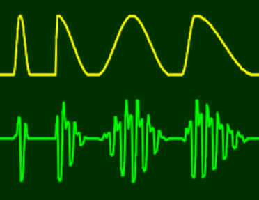
Handling external modulation is slightly more tricky though as some CV sources range from -5 to + 5 V while many range just from 0 to +5 V.
In order to make external modulation sources that are unipolar (ranging from 0 to 5 V) capable of modulating the entire range of a parameter the sensitivity of the module to external modulation is effectively twice that of internal sources, This enables things like velocity, after touch, the mod wheel and standard sequencers to fully adjust parameters without the need to multiply values by two. The slight downside of this is that it’s relatively easy for external modulation when added to a parameter’s knob value to reach maximum and minimum values when the attenuvertor is set at maximum. The resulting values are limited at the maximum and minimum values so it doesn’t have any major impact, it’s just that external modulation can therefore clip by bottoming out or topping out relatively easily.
This is not something restricted to just this module and it can actually be useful sometimes as a creative tool but it’s something to be aware of.
To give you a visual idea of what this is all about here’s an image showing how a triangular wave modulation might be affected by exceeding maximum value.
The purpose of the red line final crosshairs mentioned earlier is to enable you to see what a parameter’s final values are doing when the effects of the main knob , attenuvertor setting and internal or external modulation voltage are all combined.
Grain Parameters
Each grain has seven parameters. These are sampled at the point a grain is seeded and remain fixed throughout the lifetime of the grain.
One might reasonably think that freezing an individual grain’s parameters at the point of its creation would result in some kind of disadvantage or lack of flexibility but it actually turns out to have profound benefits.
It means that as the seven parameters vary (as a result of modulation) each grain captures and sustains a unique point in time. So even quite mundane modulations can give rise to unexpectedly beautiful juxtapositions of overlapping grains. When there are large numbers of grains playing simultaneously, each with their own unique characteristics, this can create extremely rich and lush textures that are well beyond the capabilities of conventional synthesizers.
A second benefit is computational efficiency. As much work as possible is front-loaded into the seeding of a grain (which happens just once in a grain’s lifetime) in order to streamline the work that needs to be done for each sample period (which might happen tens of thousands of times in a grain’s lifetime). This is why it’s possible to have 500 sample based VCOs, 500 envelope generators and 4,000 VCAs working inside a Granular Synth module without your computer bursting into flames.
OFFSET
This parameter controls where in the buffer the playback of a grain begins.

Because the Offset knob setting maps directly to the horizontal axis of the waveform display, another way to control offset is by a mouse click or drag on the waveform display. You will find that such mouse operations automatically change the knob setting.
When CV control is used, if the knob is set fully CCW and the attenuvertor knob is set fully CW then an input of 0 volts corresponds to the beginning of the buffer and 5 volts corresponds to the end of the buffer.
If nothing is connected to the CV input socket then the small attenuvertor knob is repurposed for internal modulation as described earlier.
The offset of a grain in the buffer can have a huge impact on what it sounds like when there is a lot of sonic variation in the sample. So often one might want to restrict the offset modulation so that grains are selected from a relatively small region of the buffer rather than them ranging over the entire buffer. So the Offset attenuvertor knob has a significantly non-linear response with much of its middle range giving fine control over small amounts of modulation.
Grain Reflection
The button labelled RFLCT (short for Reflect) controls a novel feature called Grain Reflection.

When the RFLCT button is engaged grains with offsets that go off the edge of the buffer (either earlier or later in time) are reflected back into the buffer. You could think of a ball bouncing off of a wall. This feature produces some interesting effects with sounds reversing direction.
When the RFLCT button is disengaged any grains that go beyond the limits of the buffer become silent. This can produce interesting effects too. Although be aware that it can also produce unexpected silences when you are new to how this works.
Automatic Transient Quantization of Offset
Another novel feature for controlling offset is ATQ (short for Automatic Transient Quantization).

When the button labelled ATQ (the one in the column of OFFSET controls) is engaged, new grains have their offset shifted earlier or later in time to match the nearest transient in the buffer.
Transients are automatically detected and marked by light blue vertical lines drawn on the waveform display.

Because offset ATQ works by adjusting offsets it is only really noticeable when grain offset is being modulated.
ATQ is particularly effective with moderate or fairly slow seeding rates on samples with a high rhythmic content such as drum loops but can be applied in any situation.
One interesting application is to use the APPEND button to join together a range of different samples and then use ATQ and offset modulation to select between them. When using an external sequencer module to control grain offsets you should find that ATQ makes it easier to select individual subsections of the buffer. Rather like how pitch quantization makes it easier to sequence melodies.
At higher seeding rates ATQ introduces a a degree of temporal coherence that makes textures sound less organic so one wouldn’t normally use it on things like atmospheric pads but the option is there – perhaps if you want to make a pad sound slightly more mechanical.
On its own offset ATQ enables the start point in the buffer of a grain’s playback to be quantized to a transient but there is also an option called size ATQ that works in tandem with offset ATQ. When size ATQ is engaged then the duration of a grain is automatically set to the gap between transients and the SIZE parameter is ignored. See the section on the SIZE parameter below for a full description.
ATQ SENSITIVITY
Athough automatic detection of transients works reasonably well much of the time, sometimes the Granular Synth will decide that transients are located in very strange places. Some samples just confuse the hell out of the algorithm for no apparent reason and ATQ becomes pretty useless.
But from Build #110 a new control called ATQ SENSITIVITY allows one to fine-tune transient detection. The number of transients detected increases the further to the right the slider is set.

As an example of the effect of adjusting ATQ SENSITIVITY here is the result of transient detection on the Guitar 1 test sample with the default sensitivity setting…
Notice that too many transients have been detected. But if we reduce the sensitivity by moving the slider slightly to the left the detection algorithm does a much better job of detecting the four guitar plucks…
The detection is still not perfect but you ought to be able to get reasonable results most of the time.
A surprisingly powerful possibility arises from the addition of the ATQ SENSITIVITY control as when the slider is moved fully to the left the algorithm produces just one transient at the beginning of the buffer. Therefore when size ATQ is used grains begin at the start of the buffer and their duration is the complete length of the sample.
Normally maximum grain size is limited to two seconds but with zero ATQ sensitivity and both offset ATQ and size ATQ engaged then there is no upper limit to grain size. It’s possible to have grains that last for several minutes. See the section on the SIZE parameter below for more information about this interesting new feature.
PITCH
This parameter controls the pitch shift of a grain from its natural pitch (the pitch of the sound in the buffer).

If you want to use Granular Synth sounds alongside other sound sources to create something that is in tune then it’s best if you use samples that are tuned to C. You can use the PITCH knob to retune samples inside Granular Synth but it’s far easier if the sample is already in C.
When there’s no modulation and the main knob is at 12 o’clock then no pitch shift is applied. Fully CCW results in a drop in pitch of 2 octaves. Fully CW results in a rise in pitch of 2 octaves.
The knob is calibrated in semitones so the range is -24 to +24. Note the pitch shift indicated by the tooltips is the base value before any modulation is applied.
The knob uses semitone steps so it’s pretty easy to enter precise intervals (e.g. +4 raises the pitch by a major third ) but you can also right click on the knob and select Edit Value to select shifts by typing.
The Granular Synth offers some quite sophisticated pitch control mechanisms including customizable quantization and arpeggiation that is linked to the seeding mechanism. When the seeding rate is high and/or grain size is large then arpeggiation generates granular chords.

Much of the potential of these mechanisms is tied to the Adroit Synthesis LSSP technology of S-Poly chord and scale signals. If you are familiar with LSSP this will already make sense but don’t worry if you are not as the Granular Synth comes bundled with a few modules from LSSP that enable you to generate these signal. More details later.
Quantization and arpeggiation modes are selected using a slide switch marked OMDU. This label is obviously rather cryptic but you’ll soon get the hang of it (and having full-form buttons would have taken up an awful lot of space in an already crowded GUI).
M = Mono
D = Down
U = Up
O = Off Mode
When the switch is in the O setting no quantization is applied so grains can have any pitch. This mode is suitable for more abstract kinds of sounds, special effects and so on. Although if you feed the V/OCT input with a pitch CV that is correctly tuned then you will get musical results when no modulation is applied.
M = Monophonic Mode
When the switch is in the M setting then quantization is applied so that grains will have a more musical sound. If nothing is connected to the QUANTIZE socket then the pitch is adjusted to match the nearest semitone. In other words pitches are forced to fit the chromatic scale.
However if an S-Poly chord or scale signal is plugged into the QUANTIZE socket then the pitch will be adjusted to fit the chord or scale.
U/D = Up/Down Modes
When the switch is in the U or D setting then a feature designed to create either arpeggio or polyphonic effects is brought into play.
These modes are intended to be used in conjunction with an S-Poly chord signal being fed to the QUANTIZE socket. However if nothing is connected then the module pretends that a C Minor 9th chord is plugged in. This gives you something to experiment with while learning about the module.

Unlike a conventional setup where an arpeggiator selects a note from a chord and feeds it directly to a voice, here the note selected by the arpeggiator is used as an offset to the existing pitch information. This creates far more interesting patterns than a conventional arpeggiator but the results are still highly musical because the quantization guarantees that the final pitch is still inside the chord.
AMP
This parameter controls the amplitide (or volume level) of a grain.

This is perhaps the simplest to understand of the grain parameters but its careful modulation can have a major impact on the sound of the Granular Synth. For instance by using Grain Pitch as the modulator different pitches in a granular chord can be given different emphasis. Also complex rhythmic effects can be constructed by modulating amplitude by an external sequencer clocked by SEED OUT.
Another useful AMP modulation application is cross-fading between two parallel wired Granular Synths. For instance using Voltage Modular’s MOD WHEEL output to feed both external AMP CV inputs while setting the first module’s AMP parameter knob fully CCW and its attenuvertor fully CW and the second module’s AMP parameter knob fully CW and its attenuvertor fully CCW. Then the mod wheel setting controls the mix between the two. Obviously you could use velocity or aftertouch or any other CV to do the cross-fade.
SIZE
This parameter controls the size (in other words the duration) and also the direction of play of a grain.

When no modulation is applied turning the knob CCW beyond about 10 o’clock makes grains play backwards. A small white dot indicates this critical position.
Large size settings produce a lot of overlap in grain lifetimes and therefore the cloud density increases. This can sound fabulous but be aware that CPU load increases in relation to density.
One way to mitigate this might be to negatively modulate the grain size parameter by Density. This reduces the size of new grains as density increases. Note it’s also possible to positively modulate grain size by Density. This positive feedback loop can produce some very nice chaotic explosions of sound but be aware it produces surges in CPU load. But you should be able to control this with the MAX GRAINS knob.
You may hear some people opine that it isn’t really granular synthesis if grains last more than 100 ms or the seeding rate isn’t very fast. However the Granular Synth can create some truly beautiful results with slow seeding rates and with grains that last for more than a second. Its architecture doesn’t magically change when it does this.
However we will soon be looking at using “grains” that are several minutes in length and then it probably is stretching language to describe the Granular Synth as operating in the realm of granular or microsound synthesis. Yet still the underlying architecture is exactly the same so I personally think of it as still being “granular”.
Automatic Transient Quantization of Size
The basic idea of ATQ was introduced in the discussion of grain offset control above. When the offset ATQ button is engaged then grain offsets are shifted earlier or later in time to match the occurrence of transients in the buffer sample. But there is a further level of ATQ controlled by a second ATQ button located at the bottom of the SIZE column of controls.
The size ATQ button only works when the offset ATQ button is engaged because size ATQ only really makes sense when combined with offset ATQ.
What size ATQ does is automatically adjust the size parameter of a grain so that its lifetime exactly matches the distance between the transient that offset ATQ assigns it to and the next transient in the buffer (or the end of the buffer if the start transient is the last or only transient). This takes into account any pitch shifting too. So grains pitch shifted up last for shorter periods and grains shifted down last for longer periods.
As a result of this automation the SIZE knob and any size modulation are ignored when size ATQ is active.
This probably sounds way more complicated than it is so let’s look at a practical example that plays each of the four guitar plucks in the Guitar 1 test sample at random.
You can download this simple patch by clicking on the button below.
This demonstrates the basic technique fairly well but it sounds pretty dull after a minute or two. Try changing the OMDU switch setting to U and experimenting with modulation to spice things up a little.
ATQ is well worth exploring. It’s a super easy way to chop up and reassemble samples in thousands of different ways.
ATQ SENSITIVITY and unlimited grain size
One interesting possibility is to set ATQ SENSITIVITY to zero when both the offset and size ATQ buttons are engaged.

Normally grain size is limited to two seconds maximum but in this circumstance there is no practical limit to grain size as a grain’s duration is automatically set to be the complete length of the sample in the buffer,
When recording live into the Granular Synth a limit of 60 seconds is applied for ergonomic reasons but any length of sample can be loaded as a file. Technically the maximum size of individual grains is limited to10 minutes as a precaution against accidents.
So you may be asking why is this feature useful? Well if you drop an entire song or a long vocal sample into the Granular Synth and use this facility you’ll find that it opens up a whole new world of what one might describe as slow motion granular. One way to think of this is as a form of multi-tap delay. But you can have very large numbers of “taps” each with its own pitch/speed setting, volume, fade-in/fade-out time, pan position and reverb/FX send setting.
It’s obviously very easy for grain density to exceed the 500 grain limit when grains last a minute or more so you probably won’t be routinely using this facility with audio-rate seeding! High frequency seeding won’t break anything but you’ll get a throttling effect as the MAX GRAINS setting is hit.
One fruitful technique is to seed manually by connecting a button or a keyboard gate/trigger signal to the SEED IN socket. Listening to the output you can then inject more grains at key points in time to create canon like results.
I’ve not really had chance to fully explore the potential yet but I’m sure you can be a pioneer and discover weird and wonderful sounds. Remember you can always use the envelope generator (with DEPTH set at maximum) to extract just a few seconds of the sound and maybe record the result into another instance of the Granular Synth.
Herbicide Buttons
Following on from the above you will no doubt encounter experimental situations where you have spurious grains that take forever to terminate. This is one reason why a couple of “herbicide buttons” appear next to the ATQ SENSITIVITY slider.

The red ! button on the left is deadly while the orange ! button on the right is rather more subtle.
Clicking on the red button causes all current grains to terminate and stops further seeding while the button is held down.
Clicking on the orange button causes a random two thirds of current grains to terminate and randomly reduces seeding by two thirds whilst held.
Grain termination takes up to half a second to happen (depending on where a grain is in its life cycle) so the sonic result isn’t too abrupt. Because the termination is relatively graceful the buttons can be used as creative tools to thin out the cloud in a performance situation. The orange button in particular might usefully be MIDI mapped to a control surface where you could activate it as a kind of soft pedal.
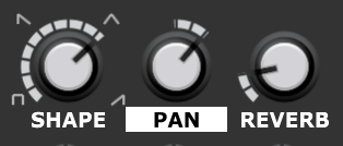
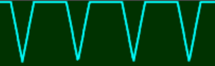
SHAPE
This parameter controls the envelope shape of a grain. This should not to be confused with the note Envelope Generator that operates at the level of the entire cloud rather than on individual grains.

Small symbols surrounding the SHAPE knob give a rough indication of how this works. The image below shows in more detail how the shape changes as the parameter moves from 0% to 100%.
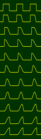
The image shows a snapshot view in 10% steps but the shape actually varies smoothly. Also note that the gap between grains varies depending on the seeding Rate and the Size parameter controls the duration of each grain envelope so this image shows just one possible situation.
Like all parameters, grain shape can be modulated rapidly as shown by the image above. This is looking at the behaviour of just one stream of grains but in practice there may be many such streams all occurring at the same time.
PAN
This parameter controls the stereo position of a grain.

Pan controls stereo balance if the sample in the buffer is stereo, but even with a mono sample in the buffer it’s possible to generate detailed stereo images.
Something that works well in almost any situation is Gaussian random modulation of Pan. As explained later, if you assign Random to the + side of the attenuvertor you’ll get Gaussian distribution while on the – side you’ll get uniform distribution. Gaussian feels more comfortable as most of the time grains will tend to be near the center of the stereo image rather than leaping about all over the place.
Another great modulation to try is Grain Pitch. This allows you to automatically pan different notes to different stereo positions. With external sequencing per grain panning can be done with precision.
REVERB
This parameter controls the amount of reverb applied to a grain.

One can think of the Pan and Reverb parameters as working together to place a grain in a two-dimensional space. Pan controlling how far to the left or right a grain is and Reverb controlling the perceived distance of a grain from the listener.
One novel aspect of the Granular Synth is that reverb is treated as a grain parameter rather than being simply added as an effect that’s strapped onto the final outputs. This has a cost in terms of CPU load but it opens up all kinds of interesting possibilities. As a whacky example it’s possible to apply reverb to just the fifth in a granular chord.
Another unusual aspect of the Granular Synth (that you may have noticed in the simplified diagram right at the top of this page) is that a voltage controlled filter is applied after the reverb rather than before. This gives the filter a real bite as it can sculpt the reverb tail whereas normally any filter modulation would be smeared by reverb applied after the filter. This meshes with the idea of reverb being a grain parameter too – the reverb is a part of a grain’s personal environment rather than a global effect. You can of course still apply additional reverb to the outputs of the Granular Synth so nothing is lost by this approach.
External FX
The built-in reverb effect is very handy but it’s possible to replace it with “outboard” effects by using the Granular Synth Breakout module.
This enables you to insert any stereo effects into the Granular Synth’s signal chain in place of the standard reverb. So you can use higher quality reverb or perhaps fancy filters, delay, chorus, distortion – in fact anything you like.
Note this is totally different to just applying such effects to the Granular Synth’s main outputs as each grain has its own individual wet/dry setting. So it’s possible to selectively apply different amounts of effects to different grains. Also the effect signals are returned back to the Granular Synth signal path and then pass through the stereo filters and the compressor.
When external effects are being applied the REVERB label changes to FX so that you know it’s no longer the internal reverb being applied.

See the Granular Synth Breakout module’s documentation for more detail.
Grain Parameter Randomization
You’ve probably already used the RANDOM button many times.
When the Granular Synth Breakout module is connected you have more control over how the RANDOM button works but for now let’s just look at how it operates normally.
When you click on the RANDOM button it randomizes the settings of the main knob, attenuvertor and both the – and + modulation sources for each of the seven grain parameters. Non-grain parameters are unaffected.
But one important thing to note is that this randomization only applies to parameters that do not have an external CV connection. In other words when something is plugged into the socket beneath a parameter’s attenuvertor it is no longer affected by the RANDOM button. So sometimes you might want to plug in a dummy cable in order to disable the randomization of a particular parameter.
A right click on any of the parameter labels (grain or non-grain) randomizes the settings for that one parameter regardless of whether an external CV source is connected.
Although the choice of sample has the most direct impact on the output of the Granular Synth, randomization is a very useful tool because the number of possible settings for the controls is astronomical. So being able to randomly explore enables one to find interesting starting places in a reasonable amount of time. But because the RANDOM button is so useful there’s a danger of over relying on it. For best results fine-tune the settings it produces and sometimes ignore the RANDOM button altogether and create settings from scratch.
Now and then you might want to automate pressing the RANDOM button by connecting a gate/trigger/clock signal to the socket on the left of the button. This can lead to wildly varying sounds but you can calm things down by disabling some randomization by plugging in cables for some parameters as explained above.
Generalized Randomization
When the Granular Synth is connected to the Granular Synth Breakout module there’s greater control over what the RANDOM button does. By default the behaviour is the same as when the Breakout isn’t connected, in other words only grain parameters are randomized.

But you can configure any setup you like using the buttons on the Breakout. For instance you might want randomization to alter the filter and LFO parameters instead of the grain parameters.
It’s possible to randomize everything at once by engaging all the buttons. This can be useful sometimes but you should be aware that you are seriously stabbing in the dark when doing this. You might find something awesome but you might end up with nothing but silence (although there is a certain amount of smart code working behind the scenes that attempts to limit “random” outcomes to something relatively sane).
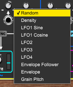
Internal Modulation Sources
External CV sources connected to individual parameter CV input sockets allow you to gain full control over modulation but to help simplify patches certain internally generated modulation sources are available when nothing is connected to a CV input socket.
To select an internal modulation source click on the + or – signs associated with an attenuvertor.
To keep things relatively simple each parameter can be modulated by only one of these internal sources at a time but given the number of parameters and range of sources this still leaves a myriad of options (and remember there are no such limitations when external CV is used).
If any of these (except random, as discussed below) are assigned to the – rather than + side of an attenuvertor then the modulation is inverted. So for instance it’s possible to make one parameter increase as the envelope rises while another parameter decreases.
Random: Each parameter has its own independent random value generator.
When Random is assigned to the negative side of a parameter’s attenuvertor the random distribution is uniform. When it’s assigned to the positive side it has a Gaussian (bell-shaped) distribution. Gaussian distribution is generally more useful as most of the time it will produce values close to the center, only rarely straying to extremes. This is closer to how many real world events occur so sounds more natural than the rather chaotic behaviour of uniform distribution.
One subtle difference with random modulation is the sample rate. Random values for grain parameters are always sampled at the point a grain is seeded but random values for non-grain parameters are sampled once per envelope cycle. However if the envelope generator isn’t looping or being fired by an external gate signal then randomization of non-grain parameters would appear not to work so when the envelope generator is “asleep” then non-grain parameter randomization occurs ever 32nd seed.
Density: A value proportional to the number of currently active grains compared with the MAX GRAINS setting. It corresponds to the proportion of the pie chart that is filled in red.

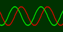
LFO1 Sine: A free-running low frequency oscillator with a sinewave shaped output.

LFO1 Cosine: The same low frequency oscillator but with the output phase shifted by 90 degrees.
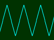
LFO2: A triangular wave LFO. If its SYNC button is engaged it will be reset to the lowest point of its cycle when an envelope attack phase begins.
LFO3: Another triangular wave LFO but this one is reset to the midpoint of its cycle by an envelope attack if its SYNC button is engaged.
The exact effect of LFO sync depends on the frequency ratios involved but it can deliver some interesting modulation waveforms as shown below.
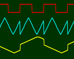
The two different ways that sync operates (lowest for LFO2 or midpoint for LFO3) offers you some interesting flexibility.
LFO4: A “wobbly” LFO with a Brownian output. This modulation source kind of simulates a user twiddling a knob in a slightly haphazard fashion. Its behaviour is a little erratic and changes character depending on its RATE setting but that’s not necessarily a bad thing.

The rate of each LFO is set by the corresponding RATE knob. The frequency range is 12 octaves from 0.005 Hz to 20.48 Hz. So at the minimum setting it takes 200 seconds to complete a cycle while at the maximum setting we are entering the low audio range. Although for LFO4 the “frequency” is obviously just a nominal notion as it doesn’t follow a fixed cycle.
There’s no built-in way to modulate the rates of the internal LFOs as there has to be some limit to the complexity of the Granular Synth. But if required Voltage Modular offers a couple of ways of gaining remote control of knobs or you could simply use an external voltage controlled LFO plugged into any of the CV inputs instead.
Envelope Follower: A value proportional to the amplitude of the module’s output signals. However if something is connected to either (or both) of the input sockets then the Envelope Follower modulation tracks the amplitude of the input instead – enabling external audio signals to have an impact on parameters. So a vast range of “side-chain” effects are possible.
Envelope: A value that tracks the built-in envelope generator. The Envelope Generator will be discussed in its own dedicated section shortly.
Grain Pitch: A value proportional to the pitch of a grain when it is created. The octave is ignored. This offers some very interesting creative possibilities – for instance making each note of an arpeggio or granular chord have a different offset, stereo position, grain size, grain shape and so on.

Grain pitch can create a wide range of patterns as it is affected by several variables (especially pitch and the setting of the OMDU switch).
Modulation Feedback
Various modulation sources are closely related to the outcomes of the Granular Synth’s operation.
Density varies in proportion to the number of active grains, the Envelope Follower (when no inputs are connected) tracks the overall output level, Grain Pitch is related to the state of the internal arpeggiator and pitch modulation, LFO2’s and LFO3’s waveforms are affected by the envelope generator when their SYNC buttons are engaged.
So these modulation sources can vary in quite complicated ways even in isolation. But being modulation sources, these complex signals can be used to modulate parameters so as to produce one or more feedback loops (where the modulation modulates the modulation).
As one example you could make the attack time of the looping envelope generator proportional to density then make the envelope modulate the filter which in turn affects the output level which in turn affects the Envelope Follower which you might use to control seeding probability which in turn affects the density and output level and we go round and round…
Such positive and negative feedback loops can produce fascinating results with sounds that exhibit slowly evolving chaotic behaviour. With a little care and patience you should be able to discover settings where the Granular Synth almost appears to have a mind of its own. The various randomization functions can help you discover strange feedback driven behaviour by chance so it needn’t be something that relies on difficult analysis or forethought.
The Envelope Generator
The Envelope Generator provides a mechanism for sculpting the amplitude of a cloud over time. It’s also a very flexible modulation source. It should not be confused with the grain shaping envelopes – these apply to individual grains. To try to avoid confusion the grain envelopes are called shapes.
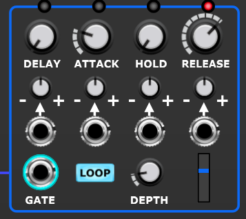
The envelope’s output value is displayed by the little blue meter and LEDs above the DELAY, ATTACK, HOLD and RELEASE knobs light up to show which phase of the envelope is currently active.

DEPTH
One very important control is the DEPTH knob. This determines how much impact the Envelope Generator has on the amplitude (volume) of the cloud.
When the DEPTH knob is fully CCW (minimum setting) the Envelope Generator has no impact at all on the cloud’s amplitude (the audio passes straight through). With this setting the Envelope Generator can be used purely as a modulation source.
When the DEPTH knob is fully CW (maximum setting) the Envelope Generator operates like a conventional synthesizer’s VCA envelope. In other words when the envelope value is at zero then no sound passes while when the envelope is at maximum value the audio is let through at full volume.
When DEPTH is set fully CW and the envelope value is at zero then the internal seeding clock stops generating grains. This massively reduces the CPU load when a Granular Synth module is not producing any sound. Note this can make a critical difference in large patches containing multiple Granular Synth modules that aren’t always running at the same time as the idle Granular Synths use up very little CPU.
Contrast this with a conventional patch that uses lots of VCOs, VCAs, VCFs, envelope generators etc – even when the conventional modules aren’t contributing anything to the sound they continue to use the same CPU resources because they don’t “know” they aren’t contributing anything.
When the DEPTH knob is somewhere between minimum and maximum settings then the Envelope Generator controls the amplitude of the cloud but some audio still passes through even when the envelope value is at zero. This can be used to create amplitude modulation (or tremolo) effects.
GATE
The GATE input accepts a regular gate signal.

If nothing is connected to the GATE input then the Envelope Generator behaves as if it is receiving a gate signal that is always high. This is indicated by the ring surrounding the socket being illuminated.
A rising gate signal resets the internal seeder clock so that it’s possible to ensure that a grain is seeded at exactly the same time as an envelope begins. This is important when tight timing is needed on transients or rhythmic effects.
However since build #107 this reset only happens when DEPTH is set fully CW and the envelope CV output is at zero. This modification was made to stop an unpleasant stuttering effect when the seeding rate was slow. This was especially a problem when playing legato with Voltage Modular set to multi-trigger mode.
LOOP
If the LOOP button is engaged then the envelope will automatically restart at the end of the release phase. If nothing is connected to the GATE input then this turns the Envelope Generator into an LFO.

If LOOP is engaged and a gate signal is connected to the GATE input then the hold phase does not sustain indefinitely (instead it just lasts for the period set) and the envelope repeats for as long as the gate is high. This is called Gated Looping mode and is useful for ratchet style sounds.
DECAY/ATTACK/HOLD/RELEASE

The Envelope Generator in the Granular Synth uses an DAHR design. It’s not the conventional ADSR design that you may be more familiar with. The reasoning being that because individual grains have their own shapes the amplitude sculpting needs are different, also much of the time you might actually be using the Envelope Generator as a sophisticated LFO with the LOOP button engaged.
One way to look at the Envelope Generator is as a four phase function generator with voltage control over the duration of each phase.
The timing range of each phase is 3 ms to 25 seconds apart from the delay time which can also be set to zero for an instant start of the attack phase (this is in fact the default setting).
To specify precise durations right click on a knob and select Edit Value. Input values are expressed in seconds so 5 would be 5 seconds, 0.1 would be 100 miliseconds and so on.
Note the durations indicated by the tooltips are the base values before any modulation is applied.
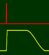
First let’s look at how things work with LOOP disengaged, the default timing settings and a medium length gate signal being applied.
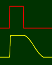
This is pretty much what you’d expect. The envelope sustains at maximum value for as long as the gate is high. This is with the minimum HOLD setting of 3 ms.
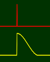
If we increase the HOLD setting so that it’s longer than the gate is high we get a longer sustain period. This is because the envelope sustains for whichever period is longest – the gate being high or the HOLD period.
The benefit of this is that one can use a trigger signal as well as a gate signal.
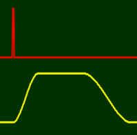
Being able to use a trigger rather than a gate is particularly useful when dealing with percussive sounds as the hold phase can be effectively skipped by using the minimum HOLD setting as shown below.
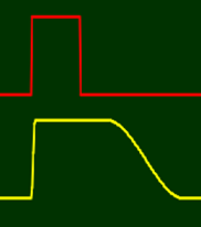
Unlike some envelope generators the attack phase is not aborted if the gate drops early as illustrated below where the ATTACK setting is increased to make this fact really obvious.
Next let’s look at the DELAY setting. This enables us to delay the start of the envelope for a while. This is useful for instance if we have a pair of Granular Synths working in tandem with one handling the attack transient and the other the main body of a note. The DELAY setting is also very useful when LOOP is engaged.

In the image above all four periods of the Envelope Generator have medium length settings,
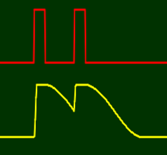
Another thing to look at is re-triggering. As you can see in the image below If a new gate signal occurs while the envelope is in its release phase it will return to the attack phase.
When LOOP is engaged the Envelope Generator acts like an LFO and each of the four timing parameters comes into play in determining the shape of its output. The fact that all of these parameters can be independently controlled by internal or external CV modulation makes the Envelope Generator a very flexible modulation source.
The image below shows the waveform when DELAY, ATTACK, HOLD and RELEASE all have the same settings.

By using modulation all kinds of bizarre waveforms can be created. For example…

The Filter
A stereo low-pass filter is applied to the outputs of the module. The FILTER knob (along with any modulation applied using the usual mechanisms) controls the cut-off frequency of this filter.

By default the FILTER knob is set at maximum in which case (with no modulation) the filter has almost no effect on the sound but by dropping the cut-off it’s possible to remove varying amounts of high frequency content.
Many granular sounds have a certain brittleness but the simple technique of applying a low-pass filter can extend the sonic range to include very warm sounds that one might not normally associate with granular synthesis.
One might sometimes turn down the FILTER knob by a small amount just to warm things up a little, but the filter cut-off can also be modulated like all the other parameters so there are many creative possibilities beyond this simple use as a treble tone control.
But the built-in filter is not attempting to be an all-singing, all-dancing, best-in-class resonant filter. Everyone seems to have their own passionate ideas about filters so it would be silly to attempt such a thing. But the Granular Synth is a module in a modular system so you can apply whatever filters you like either to the main outputs or, using the Granular Synth Breakout module, as a per grain stereo send effect as described earlier in the External FX section.
All of the internal modulation sources from a Granular Synth module are available via a connected Breakout module so you can control external filter modules parameters like cut-off and resonance (and anything else that’s voltage controllable) for effects that are fully synced with internal modulation if desired.
The Compressor
Because the number of simultaneously active grains can vary enormously a compression facility is provided in order to help tame the resulting huge variation in volume.
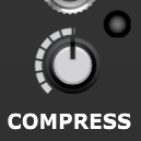
The compressor uses a fixed threshold, attack and release to simplify things. The COMPRESS knob controls the compression ratio from 1:1 (no compression) at the minimum setting all the way up to 16:1 (hard compression) at the maximum setting.
You want to sufficiently control the dynamic range so that the very quiet bits are still audible while the very loud bits don’t cause distortion but normally you should use as little compression as possible because overdoing it can take the life out of an otherwise expressive sound.
The default setting of 8:1 (with the knob at 12 o’clock) works well in most circumstances.
The LED to the top right of the knob lights up in proportion to the amount of gain reduction applied so if it’s at full brightness all of the time you might want to try adjusting other aspects of the settings (such as reducing the AMP parameter).
Outputs
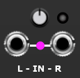
The main audio outputs of the Granular Synth are located in the bottom right of the module.
The small knob above the output sockets allows you to adjust the output levels. The LED lights up to indicate that the outputs are at or above the nominal +/- 5 V level used in Voltage Modular. It’s not an indication of clipping just a friendly warning that the output level is pretty high and might need checking.
When nothing is connected to the module’s inputs the outputs drive the Envelope Follower so it’s possible to modulate various parameters by the output level. The magenta colored meter shows the output of the Envelope Follower.
Settings
Click on SETTINGS button to display a pop-up menu of options.

The options available are all simple on/off ones. A little tick indicates if an option is enabled.
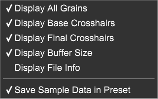
Display All Grains
When checked all active grains are shown on the Waveform Display. On an old machine with little graphics acceleration you should uncheck this option to lower the CPU load. Even on a modern high powered machine you might still sometimes want to uncheck this option to save CPU and GPU load especially if using multiple Granular Synths at once.
Display Base Crosshairs
When checked the white lines on the Waveform Display are enabled. These show the basic settings of the OFFSET parameter and one other parameter before any modulation is applied.
Display Final Crosshairs
When checked the faint red lines on the Waveform Display are enabled. These show the final settings of the OFFSET parameter and one other parameter after any modulation is applied.
Display Buffer Size
When checked information about the buffer is displayed in the top right of the Waveform Display
Display File Info
When checked information about the last file operation is displayed in the top left of the Waveform Display.
Save Sample Data in Preset
When checked the content of the buffer is stored as part of a preset (a .voltagepreset file). This means you don’t have to worry about the location or even the existence of the original sample and you can exchange preset files with someone else without any problems.
However it does mean that preset files can be rather large in size and when you have multiple presets all using the same sample data there is duplication and a certain waste of disk space.
So when this option is unchecked only the file system location of a sample is stored. However this only works if the buffer content is actually just based on a simple file load. So if you’ve just recorded something or have used Append to join several samples together then you’ll need to do an Export and then Load that new file in order to benefit from this optimization.
Most of the time it’s just easier to save the sample data in the preset as modern computers have ample storage space. Therefore this option is enabled by default.
LSSP and S-Poly
As mentioned earlier the Granular Synth’s QUANTIZE input uses S-Poly scale and chord signals.
It would have been possible to integrate certain scales and chords inside the module (as other granular synthesizers do) but this would have been rather limiting so instead the whole problem is off-loaded via the QUANTIZE socket.
The Granular Synth was designed to integrate well with the Adroit Synthesis LSSP system but it would be unfair to expect users to adopt LSSP just to access basic chords and scales. So three modules from LSSP are bundled in with the Granular Synth to give everyone access to core facilities.
These LSSP modules are called Chord, Chord Memory and 8 to 1 Poly Switch.
Skins
By default the Chord, Chord Memory and 8 to 1 Poly Switch modules use the skinning setup of LSSP so initially will look very different to the Granular Synth.
If you have LSSP then you can adopt the Granular Synth look for all LSSP modules by using the Skin module, selecting PLAIN and setting SATURATION to 0% and BRIGHTNESS to 20% (HUE doesn’t have any effect when SATURATION is at zero).

But for people who don’t have LSSP there’s a quick and easy way to make the Chord, Chord Memory and 8 to 1 Poly Switch modules have the same look as the Granular Synth and that is simply to right click on the ~Adroit~ logo at the bottom of these modules. They will then switch backgrounds. You only need to do this once as they will remember the setting. Another right click on the logo will return them to normal behaviour.
Using the Chord and Chord Memory Modules
To connect the Chord module to the Granular Synth patch its CHORD OUT socket to the QUANTIZE input as shown below.
To connect the Chord Memory module to the Granular Synth patch its CHORD OUT socket to the QUANTIZE input socket.
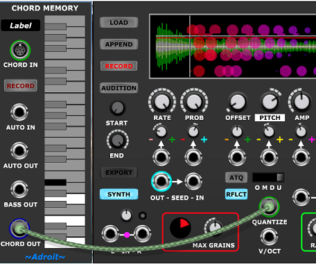
When space is not a problem you can use both modules together. This is useful as Chord Memory acts very much like Note Watcher when in record mode so for the sake of this introduction load up both modules, engage the RECORD button on the Chord Memory module and patch them together as shown below.

Then when you click on a button on the Chord module you’ll see exactly which notes are being output because the relevant keys will light up on the Chord Memory module’s keyboard graphic. The LEDs at the top of the Chord module show very similar information but in a terms of intervals rather than notes. By looking at both together while listening to the Granular Synth operating in the U or D mode you should be able to reach a quite deep understanding of how chords are constructed if this is something new to you.
So in the image above the chord selected on the Chord module is a Major chord. In C (the default) this is a chord made up of C, E and G and we can see this information displayed on the keyboard graphic of the Chord Memory module. The LEDs at the top of the Chord module indicate that the chord consists of the root note (1) a major third (the upper LED in the 3 column) and a perfect fifth (the middle LED in the 5 column).
Now select a different chord by clicking on the Minor 7th button.
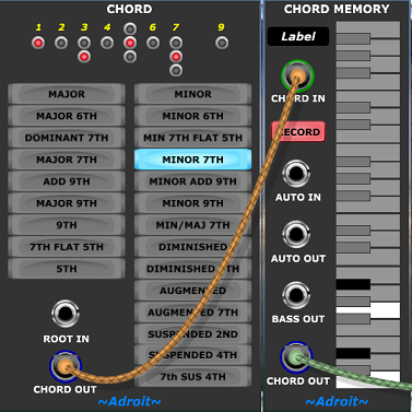
You can now see (and hear) that the minor 7th chord consists of C, Eb, G and Bb and the intervals are root, minor third, perfect fifth and minor seventh.
As a general guide the chords on the left side of the Chord module are major in flavour and have a light happy feel while those on the right are minor in flavour and have a more serious or mysterious feel.
You can change the root note of the chord by sending a regular 1 V/Octave CV into the ROOT IN socket of the Chord module as demonstrated below.
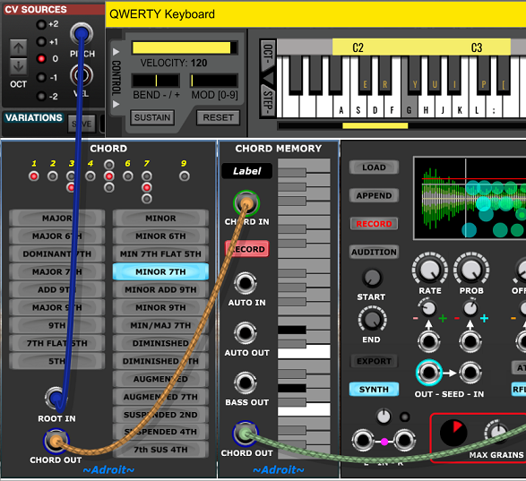
So playing F changes the Cm7 chord into an Fm7 chord.
This CV can obviously be sequenced too.
If you remove the Chord module you’ll notice that the Chord Memory module remembers what the chord was.
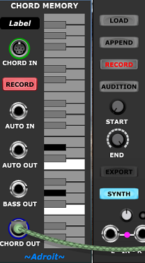
But now if you play something on the QWERTY keyboard it changes the notes stored in the memory. This is because the RECORD button on the Chord Memory module is still engaged and when nothing is plugged into the CHORD IN socket the Chord Memory module monitors whatever notes are being played into Voltage Modular and remembers them. This means that if you have a MIDI keyboard plugged in you can play chords directly on the keyboard to program the Granular Synth.
The exact details of how this works are discussed in the Chord Memory documentation. This setup isn’t really intended as a mechanism for live polyphonic playing of a Granular Synth (check out the GS MIDI X module instead). It’s just an easy way to program chords or scales. Having said that, with a little practice it can actually be used as a performance technique.
If the RECORD button is disengaged then the Chord Memory module no longer monitors what notes are being played into Voltage Modular. Instead you can edit the notes by clicking on the module’s own keyboard graphic. This enables you to construct chords and scales containing up to 15 notes.
The 8 to 1 Poly Switch module
The 8 to 1 Poly Switch module is also included in the Granular Synth bundle. This module enables you to switch between multiple chord signals in order to create chord progressions.
Normally you would sequence the chord changes by sending triggers to the STEP input of the Poly Swiitch but for more experimental effects you could try sending an envelope or unipolar LFO signal to the Poly Switch’s CV IN socket instead.
The GS MIDI X module
The GS MIDI X module is included in the bundle and greatly enhances the capabilities of the Granular Synth by enabling you to play using MIDI and not just one note at a time.

Using GS MIDI X is such a large subject that it’s treated separately here where you will also find some useful presets that illustrate the potential.
The GS Multiplex Module
The GS Multiplex module is also included in the bundle. This is a superb for multi-timbral work and interfacing with the N-Step Sequencer.
Click here for full details.
The Breakout Module
An optional add-on for the Granular Synth is the Granular Synth Breakout module. This connects via a pair of S-Poly cables and enables you to deeply integrate Granular Synth with other modules.
All of the internal modulation signals become available to control anything in your patch and the internal reverb can be replaced by any kind of audio processing you like.
A range of buttons enable you to extend and customize what the Granular Synthesis RANDOM button does.
It also includes three little utilities to help with signal processing tasks.
For full details check out the Breakout module’s dedicated documentation page.
Shortcuts
A right click on the label beneath any of the main knobs randomizes the knob’s setting, the associated attenuvertor and both + and – internal modulation sources. This is extremely useful for exploring changes to a single parameter while leaving everything else intact.
To reset all the knobs and buttons to their default setting right click on a blank part of the module and select Reset Controls from the menu.
Reset Controls does not throw away the data in the buffer.
Note the Randomize Controls option is this menu is not very useful. The Granular Synth’s RANDOM button does a much better job.
It is often useful to reset a single control to its default value. You can do this by right clicking on the control and selecting Return To Default Value from the menu.
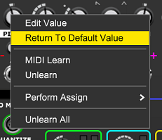
Alternatively, you can configure Voltage Modular’s Settings to reset a control with a double click.

This option is in Voltage Modular’s Setting | Interface menu. The wording is rather ambiguous. You don’t need to do a CTRL double click, it’s just a regular double click.
Troubleshooting
No or very little sound
Output not connected
No sample loaded
PROB set at zero
AMP set at zero
Output adjust control set at zero
Gate input low and DEPTH set at maximum
RATE set very low
FILTER set very low
Very short envelope
Very long envelope DELAY
Offset scanning quiet part of sample
RFLCT button disengaged and offset scanning outside of buffer
Not recording
Input adjust control set at zero
Envelope Follower not seeming to work
In Synth mode the envelope follower still follows any inputs connected, disconnect the cables if you want to follow the output signal instead
CPU overload
Try reducing MAX GRAINS, deselecting Display All Grains in SETTINGS and/or using a mono rather than a stereo sample
Inside the Granular Synth
Textual descriptions of complex systems can be a little ambiguous so this technical appendix presents a couple of schematic style diagrams showing more precise information about the internal architecture of the Granular Synth.
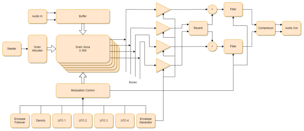
The diagram below shows what’s inside the 500 Grain Voice blocks in the diagram above.
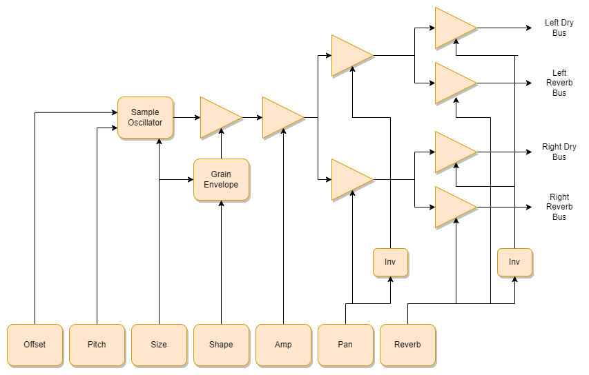
These diagrams still show a rather simplified view of things and lots of details are missing but they will hopefully offer some insight for the more technically minded user wanting to dig deep into the Granular Synth.
Availability
The Granular Synth bundle consists of the main Granular Synth module along with the Chord , Chord Memory, 8 to 1 Poly Switch, GS MIDI X and GS Muliplex modules and is available for download here.
Please note that the GS Breakout module is not included in the bundle.