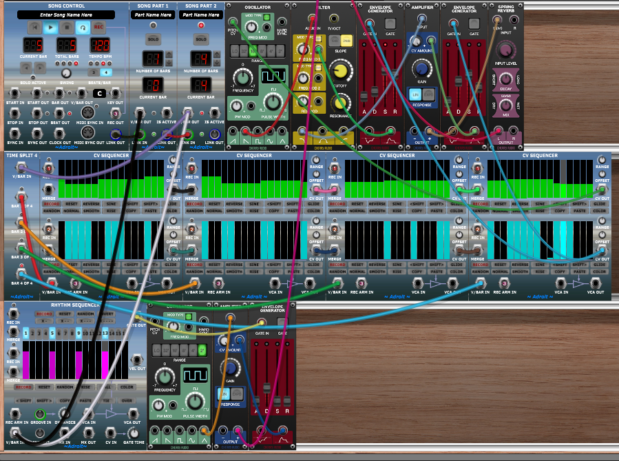
This tutorial begins where Tutorial 3 left off. So start by loading the Tutorial 3 patch into Voltage Modular…
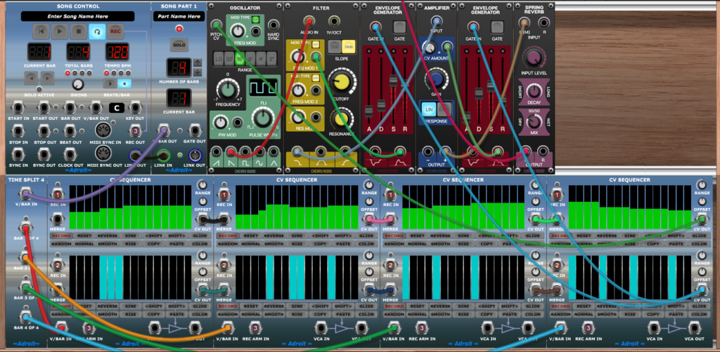
One thing you will likely have noticed is that when PLAY isn’t engaged the keyboard has no effect, so it’s impossible to practice without having to record at the same time.
This is easily fixed by patching the PITCH and GATE signals into the MERGE inputs of the first CV Sequencer. Then when all of the sequencers are inactive (because PLAY isn’t engaged) the keyboard’s signals will be passed down the chain module by module until they reach the test-bed synth.
Use the same right-click menu method as employed in Tutorial 3 to assign Bus 1 to the upper MERGE socket of the first CV Sequencer and Bus 2 to the lower MERGE socket.
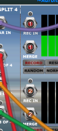
Playing a key should now make the test synth sound as one would expect.
Next let’s add a metronome so that we can get a sense of timing rather than trying to guess were the beat is when recording. This also gives us an opportunity to introduce the Rhythm Sequencer module.
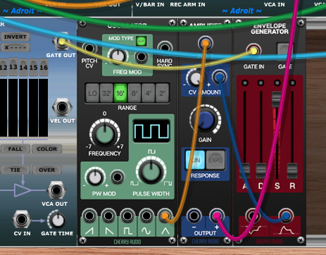
Add a Rhythm Sequencer module in a new cabinet at the bottom of the existing patch. We then need a simple sound generator for the metronome so add another Oscillator, Amplifier and Envelope Generator next door…
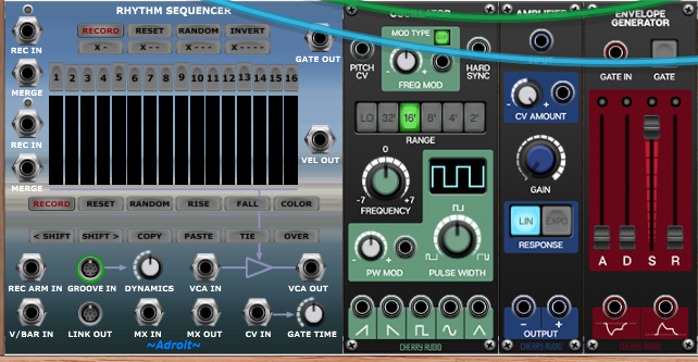
Patch the Rhythm Sequencer’s GATE OUT to the Envelope Generator’s GATE IN.
Connect the oscillator’s Triangular Out socket to the Amplifier’s INPUT.
Connect the Envelope Generator’s positive output (the bottom right socket) to the Amplifier’s CV AMOUNT socket.
Then connect the Amplifier’s + OUTPUT to the 1R MAIN OUTS socket at the very top of the Voltage Modular window.
Patch the Song Part module’s V/BAR OUT socket to the Rhythm Sequencer’s V/BAR IN socket so that the Rhythm Sequencer plays in time with the CV Sequencers.
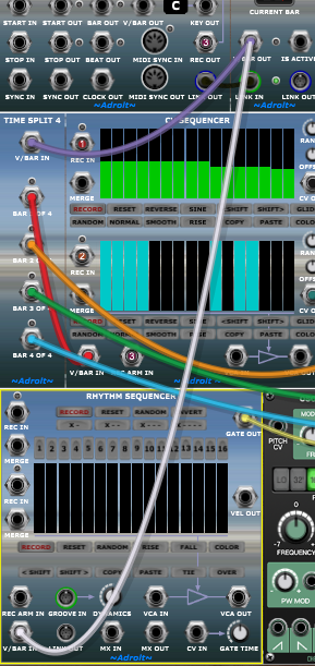
Now click on the Rhythm Sequencer’s X – – – button to program a “four to the floor” pattern.
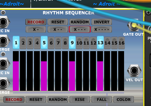
The X – – – notation means On, off, off, off. This on/off pattern is repeated over the 16 steps so we end up with steps 1, 5, 9 and 13 on. This pattern marks the four beats of a regular 4/4 time rhythm.
To hear the effect press the PLAY button.

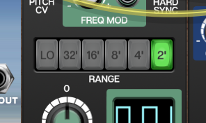
The metronome is barely audible so change it’s Oscillator’s Octave setting to 2′ to make it stand out. It’s weird that some people still use the length in feet of pipe organ components to indicate pitch, but there you go.
The metronome sound is kind of like a beep at the moment so adjust the Envelope Generator’s sliders to turn it into something more like a click…
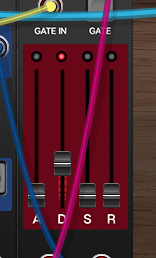
So now we should have the test-bed synth playing in the left channel and the metronome ticking away in the right, But of course they will be completely out of time because the recording was just randomly input with no sense of where the beat was.
You can try re-recording, now with the metronome as a guide, but it’s still very difficult to get the timing right. Slowing down the recording tempo helps a lot but what’s really needed is a “count-in”. In other words having the metronome play 1-2-3-4 before recording starts so that we already know where the beats are.
This gives us an opportunity to use multiple Song Part modules for the first time.
We can treat the single bar count-in as one part of a song and the four bar main section as another.
This demonstrates an important operation in LSSP – extending a composition by inserting a new section. It also shows why Song Control and Song Part are separate modules.
So simply add a new Song Part module positioned between the existing Song Control and Song Part modules.
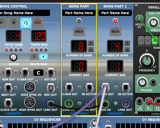
There are a couple of things to note here. Just because the new module is positioned here doesn’t mean it automatically becomes part of the Song Control Sequencer. It has to be wired up.
In a large composition there might be lots of Song Part modules and making sure they are wired up properly after a change is important. There are a couple of features built in to help.
Firstly there’s a little green LED between the LINK IN and LINK OUT sockets. This LED is kind of like a health check. Literally a “green light” saying that everything is wired up properly.
The second is the module’s title. Note that on the new module it just says SONG PART rather than SONG PART 1 or SONG PART 2.
Let’s change the wiring so that the new module is inserted properly…
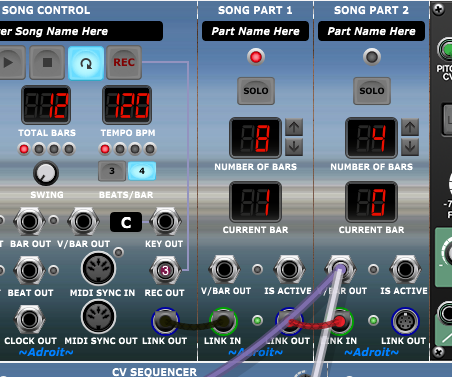
So now the LINK IN and LINK OUT connections make sense and the green lights of both Song Part modules are on and their titles are SONG PART 1 and SONG PART 2. So everything is as it should be.
Also note that the TOTAL BARS readout on the Song Control module has changed from 4 to 12 bars, the sum of the Song Part modules’ NUMBER OF BARS.
We only want a 1 bar count-in so use the little down arrow button on Song Part 1 to reduce the number of bars to 1. Just as you would expect Song Control keeps track and changes TOTAL BARS to 5.
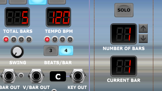
If you press PLAY now (with LOOP engaged too) you’ll hear a silent one bar lead in then the four bar main section. The 5 bars will repeat over and over. The count-in is silent because the Rhythm Sequencer isn’t yet connected to the V/BAR OUT socket of Song Part 1.
Add that cable…
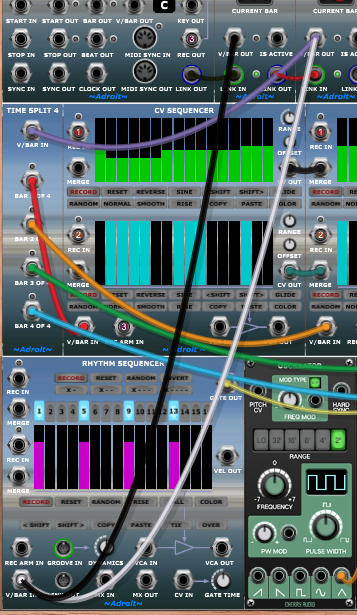
You should now get a one bar count-in with just the metronome playing then a four bar section with both the metronome and main 64 step sequencer playing.
We could have saved a cable by patching the Rhythm Sequencer’s V/BAR IN socket to the Song Control V/BAR OUT socket instead. But using two cables illustrates that multiple Song Parts can drive the same sequencer (or bank of sequencers). Something useful for instance when a chorus is repeated in a song.
Note that to perform recording you now need to click on the REWIND TO BEGINNING button to make the Song Control Sequencer go back to the very beginning. Then click on REC. Then PLAY.

Hopefully with the metronome, a slow recording tempo and the 1-2-3-4 count-in you will be able to record keyboard input with some fidelity after a little practice.
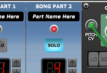
After recording you won’t want the count-in to play when looping, but it’s easy to drop the count-in by simply clicking on Song Part 2’s SOLO button. SOLO isolates a single Song Part and is very handy when editing a song with multiple parts.
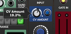
Also you can turn down the metronome by adjusting the CV AMOUNT knob on the Amplifier module at the bottom of the patch.
Save the patch as a preset called Tutorial 4.
This patch isn’t going to replace a DAW’s recording facilities of course, but it demonstrates several aspects of LSSP that you will be able to apply in other situations.
