Click here for an introduction to the Granular Synth and the main reference material.
Also be sure to check out the separate documentation and various demo presets covering the GS MIDI X and GS Multiplex modules.
Table of Contents
Minimal patch
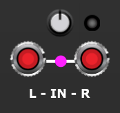
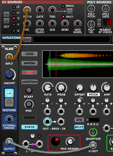
The simplest patch is just a single Granular Synth connected to the main outputs of Voltage Modular…
A few demonstration presets for this basic setup are provided below.
Presets can be useful for getting a feel for things and learning basic techniques but as you can load up any sample that you can lay your hands on and the internal modulation system has 100 trillion routing possibilites the best option is perhaps to jump in the deep end and experiment. This way you will find sounds that nobody else on the planet will ever hit upon.
Randomization can often be helpful for discovering a good starting place – use the RANDOM button or right click on any of the labels beneath the main knobs to take stabs in the dark. The action of the RANDOM button can be fine-tuned if a Breakout module is attached.
A word about reverb
Although the Granular Synth includes reverb functionality it’s worth noting that this is not really intended as a substitute for reverb or delay effects being applied to the output of the module. The internal reverb does help with spatializing, especially in conjunction with pan control, but a major part of its role is as a diffusion effect – optionally blurring grains into something more like a cohesive wall of sound rather than lots of individual elements.
The internal reverb is slightly unconventional as it’s applied as a stereo send where each grain has its own send level. So with modulation applied different grains can have different amounts of reverb. Also the internal reverb is mixed in with the dry signals before the filter and compressor. So if the filter cut-off is varied this affects the sound of the reverb.
So sending the output of the Granular Synth through an external reverb/delay effect can be very useful. And because many of the sounds the module produces are rather avant-garde the recommended tool for this job is the Valhalla Supermassive plugin. This wonderful plugin is free and it complements the Granular Synth so well because it can produce such out-of-this-world effects.
To use Supermassive download the plugin and use the Voltage Modular Mini Plug-in Host to access it in a patch.

If you have the optional Granular Synth Breakout module then you also have the option of using Supermassive (or any other effect) as an alternative to the internal reverb.
Another interesting possibilitiy is modulating Supermassive’s parameters using the Plug-in Host CV facility.
Presets that use plugins aren’t including here due to them being dependent on your machine and where the plugins are installed.
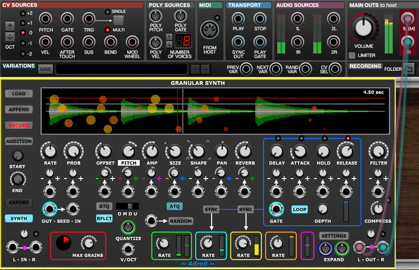
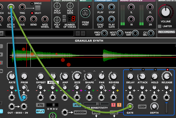
Gate control
When using a keyboard you’ll likely only want to hear sounds in response to key presses. The most straightforward way to achieve this is to use the Envelope Generator to control the volume of the cloud. Patch the I/O Panel‘s GATE output to the Granular Synth’s GATE input and make sure that the Granular Synth’s LOOP button is disengaged and the DEPTH knob is turned fully clockwise (CW).
In this situation a held key keeps the envelope at maximum value until it’s released.
If the duration set by the HOLD parameter is longer than a key press then the hold phase will be extended.
If you want a purely percussive envelope with no hold phase then use the TRIG output from the I/O Panel instead of GATE and set HOLD to minimum.
When using a trigger as a gate you can use the HOLD parameter to control exactly how long the envelope hold phase lasts as the gate (being a brief trigger pulse) has no effect on this.
If the LOOP button is engaged at the same time as a gate is connected then the Envelope Generator operates in Gated Looping mode.
Pitch bend
When using the Granular Synth as a mono-synth you might want to add pitch bend.
You’ll need to set the OMDU switch to Off in order to get pitch bend effects otherwise the quantization will make the pitch jump instead of slide. Also because a grain’s pitch is fixed at the point it is seeded then pitch bend will only work when the seeding rate is high enough for there to be a rapid stream of grains. Then although each individual grain still has a fixed pitch the perceived result sounds like pitch bend. It’s kind of an auditory illusion.
When RATE is turned up to audio-rates you might hear some unpleasant ring modulation like sounds but with a little modulation of parameters you can get beyond this. For instance click on the + sign in the RATE column of controls and select LFO1 Sine from the menu and turn up the attenuvertor very slightly. Then the seeding rate will change over time. PITCH or OFFSET modulation works well too. By modulating several parameters with different modulation sources the sound begins to evolve more organically.
If you try adjusting the pitch bend wheel on your keyboard you’ll find it has no effect on the Voltage Modular I/O Panel‘s PITCH output. This is because pitch bend only produces a change in the CV signal from the BEND output on the I/O panel.
The BEND signal varies between -5 V and 5 V so needs attenuating to be practical unless you want pitch bends that go up and down by five octaves.
Voltage Modular provides a handy module called Bend Limiter for this purpose.
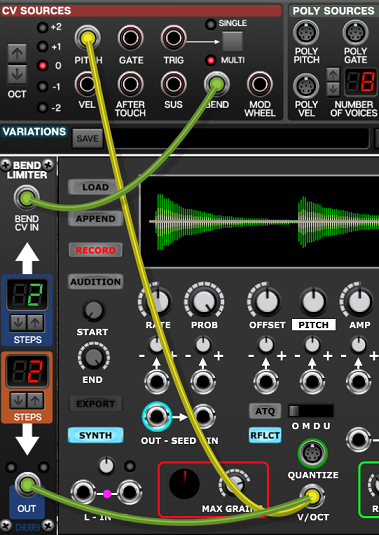
So in the simple patch shown above the pitch bend wheel on your keyboard will have a plus or minus two semitone range.
You could skip the Bend Limiter module and patch the BEND directly in to the CV input of the PITCH parameter as shown below.

But it’s more difficult to trim the attenuvertor to limit the bend with precision and by using the CV input it means there’s no longer easy access to internal modulation of pitch.
Vibrato
Vibrato can also be applied using a very similar mechanism to the one described above for pitch bend.
Typically one would use a keyboard’s mod wheel to control vibrato. The mod wheel setting is available as a CV signal from the I/O Panel’s MOD WHEEL output. It has a 0 V to 5 V range.
A module called the Mod Wheel Assistant is useful here. It’s essentially just an LFO with a built in VCA to control the amplitude of its output. Here’s how you might initially wire it up…
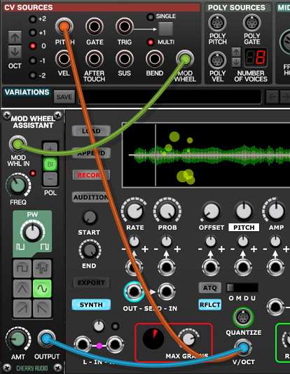
The default FREQ setting is 6 Hz which is a good starting point as conventional vibrato rates range from about 4 Hz to 8 Hz. Obviously you are free to break convention but high modulation frequencies will only work if the seeding rate is considerably higher than the modulation rate.
Unfortunately the output signal from the Mod Wheel Assistant seems not to have been designed with realistic vibrato in mind as it’s not possible to set the AMT (amount) control to low enough settings to get subtle vibrato. Sometimes vibrato only needs to be in the range of plus or minus half a semitone (+/- 1/24 of a volt). This equates to an AMT setting of less than 0.01 so an additional module is required to scale down the output.
One could just use a general purpose attenuvertor but it makes more sense to use a Bend Limiter as this also gives fine scale control of the bi-polar range. So here’s the recommended way to patch vibrato…
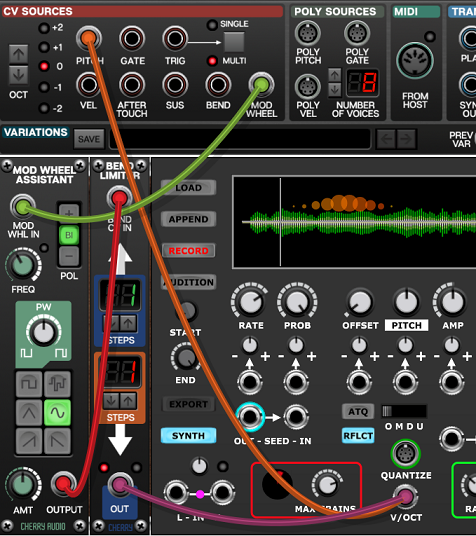
With this setup you can use the Mod Wheel Assistant’s AMT knob and the Bend Limiter’s up and down steps settings combined to gain precise control. So in the patch shown above because the AMT knob is set at 0.5 and the up and down settings are one then the range of vibrato is plus of minus half a semitone. This setup gives one the additional advantage of being able to scale the positive and negative parts of the vibrato independently.
A good alternative to using the mod wheel to control vibrato depth is to use the AFTER TOUCH signal instead.
Pitch glide
The basic mechanism used for pitch bend and vibrato can also be used to create portamento effects.
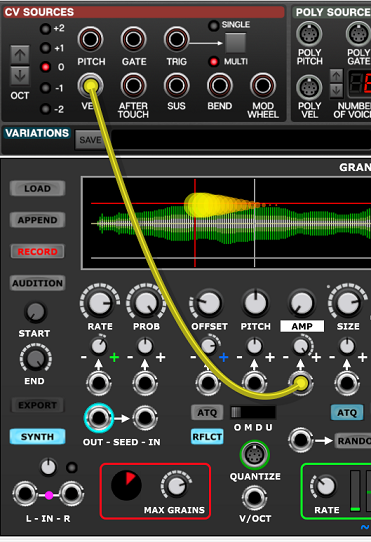
Simply insert the Glide module in the path from PITCH to V/OCT as shown below.
Velocity control of amplitude
To adjust the amplitude of grains so that they respond to how quickly keys are pressed patch the I/O Panel’s VEL socket to the Granular Synth’s AMP CV in socket and adjust the AMP knob and the associated attenuvertor to get the desired response.
The VEL output ranges from 0 V to 5 V but each keyboard behaves slightly differently so you may need to tweak things to get the best feel. Budget keyboards tend to have rather hit and miss velocity response compared with higher-end keyboards.
The Expression patch
The following patch demonstrates the techniques discussed above along with aftertouch control of offset and a little bit of internal modulation.

Gated seeding
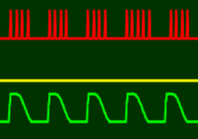
The seeding clock stops running under certain circumstances. Because grains are then no longer being created this lowers the CPU load significantly (something that might be very useful when multiple Granular Synths are running).
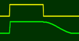
When the DEPTH knob is set at maximum and the envelope falls to zero there is no point in seeding further grains as they would not be heard.
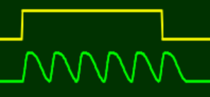
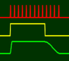
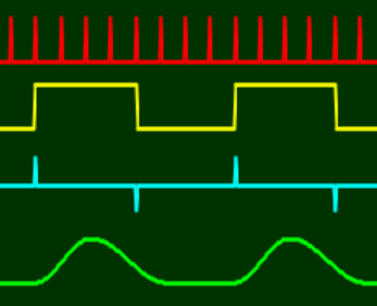
This situation is shown below. With the seeding clock output shown in red, the gate shown in yellow and the envelope shown in green. Notice how the seeding clock keeps running until the envelope release has completed.
Alternatively you could use the gate CV to control probability in order to turn the seeding clock off as soon as the gate drops…
Indeed we could do this even without involving the Envelope Generator (say with DEPTH fully CCW).
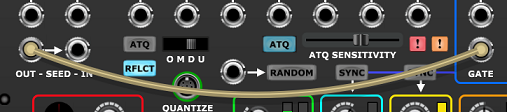
To turn the seeding clock on and off with a gate signal patch the gate to the PROB CV input, turn the PROB knob fully CCW and the attenuvertor fully CW. This makes the probability either 0% or 100% depending on whether the gate is low or high.
Another situation where the seeding clock stops is when nothing is connected to the GATE input, LOOP is engaged, DEPTH is fully CW and the envelope DELAY duration is non-zero.
The clock then stops when the envelope generator is in its delay phase.
A related situation is when a gate signal is added in order to put the Envelope Generator in Gated Looping mode…
Tempo synced seeding
One might sometimes want to generate grains in sync with tempo, especially when running at a relatively slow seeding rate. This is easily achieved by clocking the Granular Synth via its SEED IN socket.
Let’s say you want a grain to be seeded every 16th note relative to your DAW (or the built-in tempo clock when running Voltage Modular in standalone mode).
The I/O Panel SYNC output provides a 96 PPQN clock that we can utilize. By passing this through a Sync Divider module it’s straightforward to seed at a timing ratio relative to the tempo.
The SEED IN socket can be used to sync to a wide range of sources including the SEED OUT signal from another Granular Synth.
Plugging a cable into the SEED IN socket disconnects the internal seeding clock from the grain engine but the seeding clock signal is still available via the SEED OUT socket so can be used for other purposes if desired.
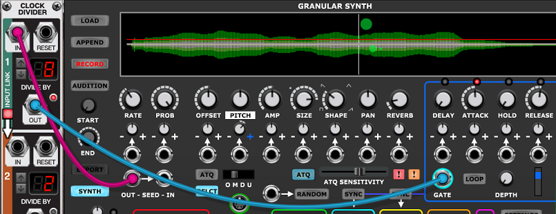
Using SEED OUT as a GATE
You can patch the SEED OUT signal to the GATE in socket of the same Granular Synth. This makes the envelope generator fire each time a grain is seeded. This only really works with relatively slow seeding rates as the envelope generator isn’t designed for audio-rate cycling.
Also this isn’t much use for modulating grain parameters because these are frozen at the point of seeding, but it is useful for creating per-grain filter sweeps and to gain detailed voltage control over grain shape by setting the SHAPE knob fully CCW and using the Envelope Generator and its VCAs to do the amplitude contouring.
However, you should be aware of a problem that you might encounter if you use this technique when DEPTH is set fully CW. As described above the seeding clock will stop running when DEPTH is fully CW and the envelope falls to zero. So in this circumstance both the seeding clock and the envelope generator will freeze. Backing off the DEPTH knob very slightly fixes the problem.
If you want the seeding clock to only run when a key is pressed then also patch the I/O Panel’s GATE output to the Granular Synth’s PROB CV in socket as described above in the Gated seeding section.
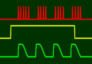
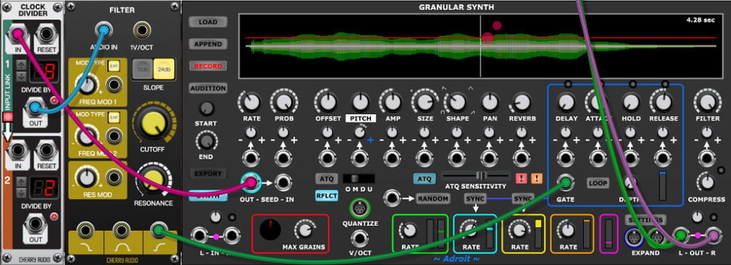
The seed out to gate arrangement can be made more flexible by inserting a Clock Divider between the SEED OUT and GATE. This enables you to fire the Envelope Generator say every fourth or eighth seed. Then envelope modulation of grain parameters works (because the seeding rate is a higher frequency than the envelope cycle) and it opens up a number of interesting rhythmical possibilities.
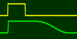
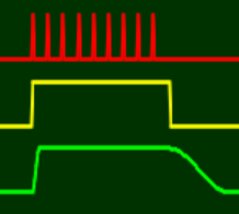
One limitation of the patch shown above is that the Clock Divider produces a square wave output rather than a trigger and this makes the Envelope Generator’s hold phase last for longer than one might sometimes want. This is illustrated below with SEED OUT shown in red, the output of the Clock Divider shown in yellow and a typical envelope this might produce shown in green…

The thing to note is that the hold phase of the envelope can’t be shortened in this patch as the GATE signal is always high for half of the cycle.
To get around this we need to convert the square wave output of the Clock Divider to a trigger. This requires a Gate To Trigger module but unfortunately there isn’t one in the Voltage Modular Core bundle. But it’s not a major problem as we can use the standard Filter module as a high-pass filter to achieve this.
A more compact and neat solution is to download Nick Hladek’s free Gate to Trigger module but we’ve used the standard Filter here instead as it’s included in Voltage Modular’s Nucleus bundle so is automatically available to everyone.
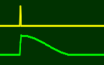
Although the Filter module is mostly intended for audio use it works with any old voltage. Just using the default settings the high-pass output detects the rising and falling edges of the square wave and outputs a brief positive spike on the rising edge and a negative spike on the falling edge.

The negative spikes don’t have any effect when fed to the Granular Synth’s GATE input but even though the positive spikes don’t reach 5 V they are just high enough to be detected as valid trigger input.
Here’s what all the signals involved look like…
Notice that the envelope hold phase is much shorter than before. In fact its duration can now be fully controlled by the HOLD parameter. So this setup is far more flexible than without the filter.
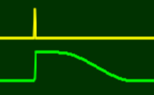
This might all sound a little abstract so here’s a patch that demonstrates the technique.
Note this patch doesn’t sound particularly impressive. It’s kept very simple in order to demonstrate the technique without distraction. All that’s happening is that the Envelope Generator is being triggered every 8th seed and the pitch of grains is being modulated by the envelope.
By the way if all you want is to do is tempo sync the Envelope Generator a simpler option is to use a Sync Divider (which has the advantages of outputing a trigger rather than a square wave).
Using external sequencers clocked by SEED OUT
Using the Granular Synth’s SEED OUT signal to clock external sequencers and using their outputs to feed back into the Granular Synth opens up a wide range of possibilities some of which are discussed below. The easiest route is to start off with Voltage Modular’s standard Eight Step Sequencer.
You are almost certainly already very familiar with how this sequencer works but if not then you should definitely read the documentation and experiment with it. It’s pretty easy to use and perfectly capable of delivering all the basics.
When using this technique it’s best to begin with a single sequencer at slow seeding rates to get a good understanding for what’s going on. But with faster seeding/sequencing rates there’s a qualititive change where the sequencing is no longer perceived as actual sequencing. For example you might use fast arpeggiation and grain overlap to create say a five note granular chord then use a sequencer with five steps to contol PAN. When the rate is fast enough it no longer sounds like the pan is being sequenced. Instead each of the five sliders controls the stereo position of one of the notes in the chord. This is demonstrated by the Panned Chord preset later on.
Once you’ve mastered the basic technique you can use many parallel sequencers each controlling any of the 14 CV controllable parameters of a Granular Synth and of course experiment with different numbers of steps for each sequencer and use clock dividers to add even more spice.
Sequencing rhythmic seeding patterns
Normally seeding happens at a regular pace. This can be changed by modulating RATE or by manipulating probability via the PROB parameter but another technique is to program rhythmical patterns using a sequencer inserted between SEED OUT and SEED IN.
To set this up you need to patch SEED OUT to the sequencer’s EXT CLK and the sequencer’s TRIG OUT to SEED IN. Then engage both the EXT and play buttons on the sequencer.
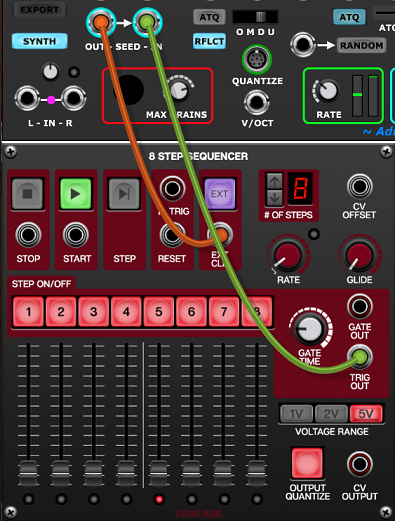
This won’t do anything useful until you click on some of the red STEP ON/OFF buttons. Then you will find that you can introduce rests in the seeding pattern. For instance if you disengage the buttons for steps 2 and 5…
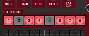
…this will produce a rhythmical seeding pattern like this…
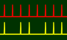
Note that without something else to mark the 1 you’ll actually hear this as a 2-4 pattern rather than a 1-2-3 pattern.
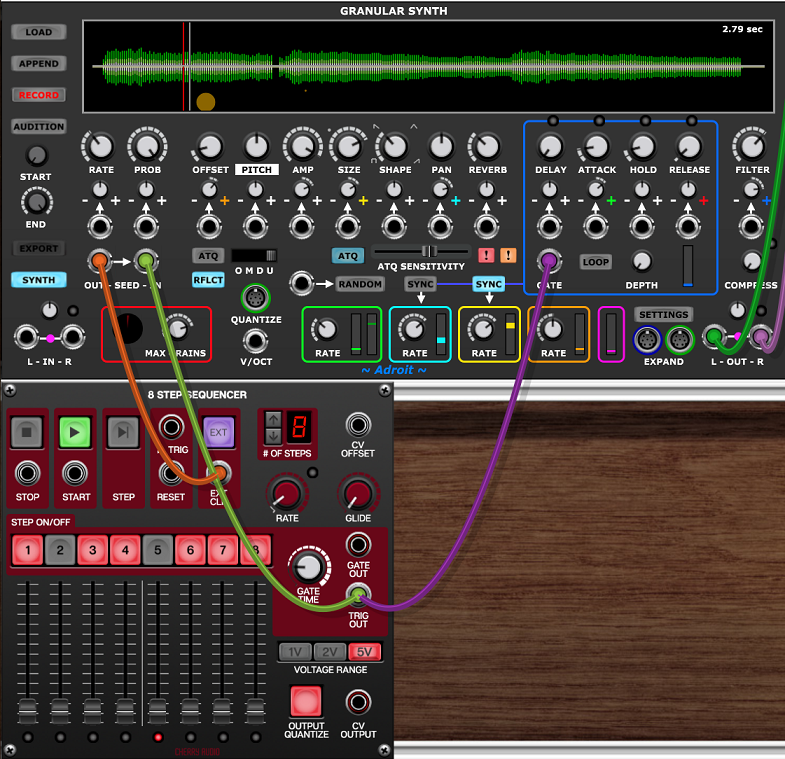
Here’s a patch exploiting this seeding pattern…
Sequencing grain pitch
Perhaps the most obvious thing to do with an Eight Step Sequencer clocked by SEED OUT is to program pitch sequences by patching its CV OUTPUT to the V/OCT input of a Granular Synth with its OMDU switch set to Mono.
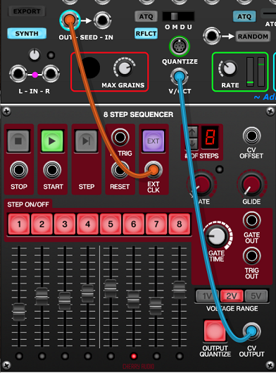
The following patch delivers the kind of cliché sound that one might expect from using this technique.
The pattern can be altered by adjusting the sequencer’s sliders and by clicking on the STEP ON/OFF buttons
The Chord module feeding the QUANTIZE socket makes things sound slightly more musical as it restricts the pitches available. Try selecting different chords for different flavors or remove the Chord module if you prefer something that’s purely chromatic.
The filter sweep sound is part of the sample rather than provided by the Granular Synth’s own filter. The apparent filter modulation is actually just LFO 4 (a Brownian LFO) modulating OFFSET.
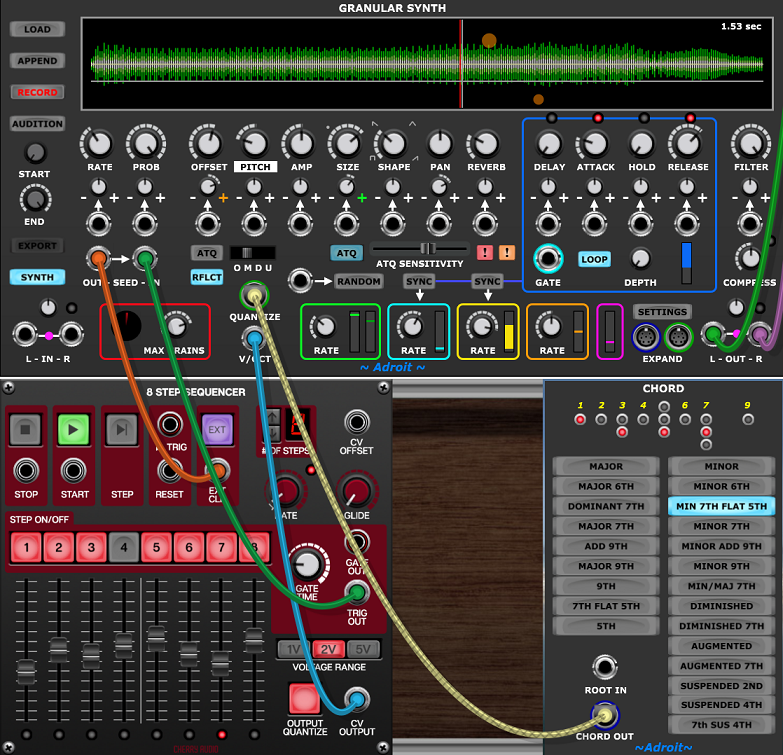
Panned chord
As mentioned earlier when the seeding rate gets above a certain threshold there’s a perceptual shift in how seeding-clocked sequencing sounds. The following patch demonstrates this effect.
This is perhaps best listened to on headphones.
Initially all five notes of the default Cm9 chord are on the hard left of the stereo image but if you play with the first five sliders of the Eight Step Sequencer you will hear that each note can be positioned independently.
Click on the PAN label to see a visual representation of the panning in the vertical positioning of the grain circles.
Parametric chord
Once you understand how the Panned Chord patch works you’ll no doubt see that this idea can be extended to multiple parameters.
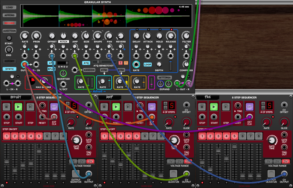
Here we have 15 sliders across three sequencers giving control of grain offset, amplitude and pan for each note of the default Cm9 chord.
The offset and size values are quantized as both ATQ buttons are enaged. This slightly complicates things but the result is very musical. Essentially you can reconfigure the chord slightly by tweaking the faders on the left hand sequencer. This works because the sample in the buffer contains elements with different but closely related pitches.
For more fun one can add a Chord Memory module and connect its CHORD OUT socket to the Granular Synth’s QUANTIZE input. Then click on the Chord Memory’s little built-in keyboard. Widely spaced chords work well. As all the sequencers are set to a five step sequence you’ll find that five note chords are stable whilst ones with less than or more than five notes produce mutating patterns.
Here’s the patch with a Chord Memory module added…
Using multiple Granular Synths in a patch
There are lots of reasons why you might want to use multiple Granular Synth modules in a patch, but if you are running on an old or low budget machine the CPU and GPU overheads might stretch your computer’s resources, so here are a few efficiency tips.
Aim to minimize the total number of simultaneous grains being produced without this having a negative impact on the richness of the sound.
Check out the “Gated seeding” section above and try to arrange for any Granular Synth that’s not currently adding anything to the sound of a patch to shut down its seeding clock.
There’s no point in having a Granular Synth’s RATE, SIZE or MAX GRAINS set high if reducing these doesn’t have a noticeable impact on the sound.
Try controlling overactive Granular Synths by applying negative feedback. For instance negatively modulating RATE , PROB or SIZE by density so that as the number of grains increases the rate of seeding and/or the lifetime of grains is reduced.
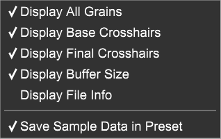
Try unchecking Display All Grains in the SETTINGS menu.
Use mono rather than stereo samples unless there is some interesting stereo information in the sample that is audible in the final mix.
Cross-fading
Cross-fading between two Granular Synth modules can be achieved by modulating the AMP parameter of each module in opposite senses.
When using an external CV ranging from 0 V to 5 V if one sets the controls the following way…

…then the amplitude ranges from 0% to 100%.
But if one sets the controls the following way…

…then the amplitude ranges from 100% to 0%.
So sending the same 0 V to 5 V signal to two Granular Synths, one with AMP controls set one way and the other set the other way enables the control voltage to cross-fade the amplitude of the two modules.
Here’s a simple patch that demonstrates this…
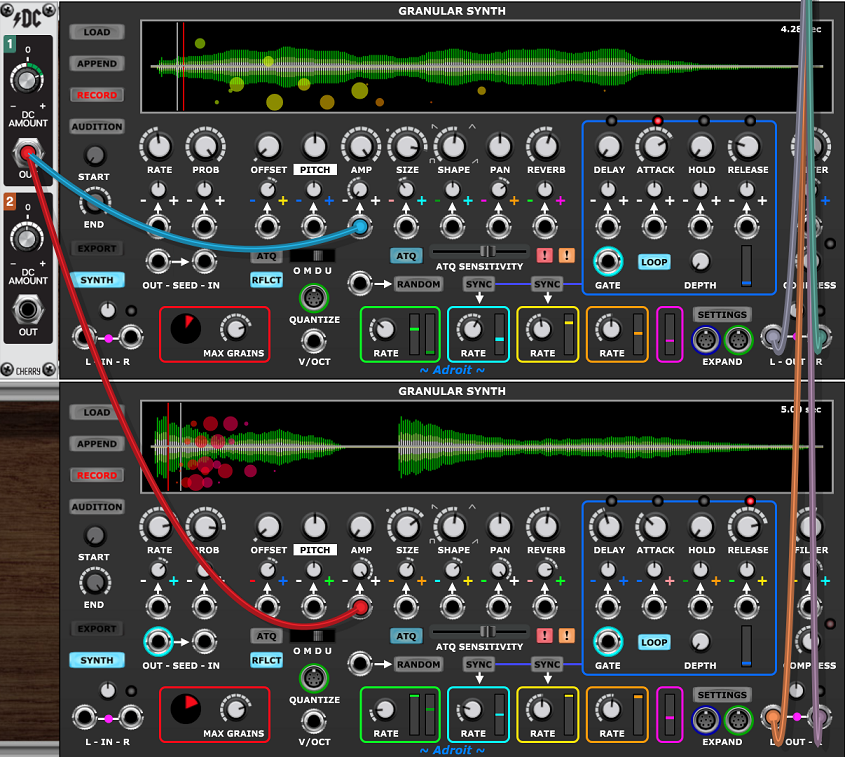
The top knob of the DC Source module controls the fade between the two Granular Synths. At 12 o’clock (0 V) only the top one is audible, fully CW (5 V) only the bottom one is audible. The two sounds in this patch are quite similar in order to demonstrate just how subtle yet complex the effect of cross-fading can be, but you can of course use highly contrasting sounds instead.
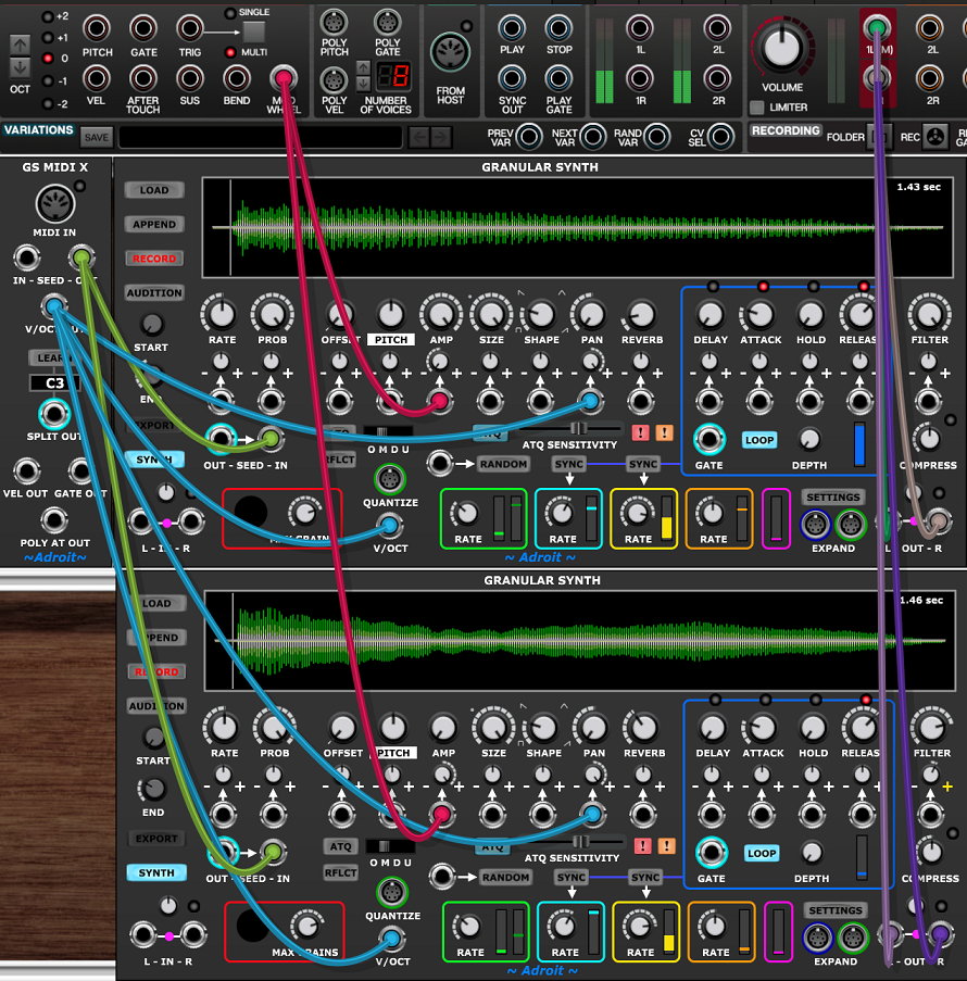
In practice you’d use maybe the mod wheel, velocity, after touch, an envelope or some other CV source to control the cross-fade. Here’s an example (using GS MIDI X) where the mod wheel morphs the sound between an acoustic and an electric piano…
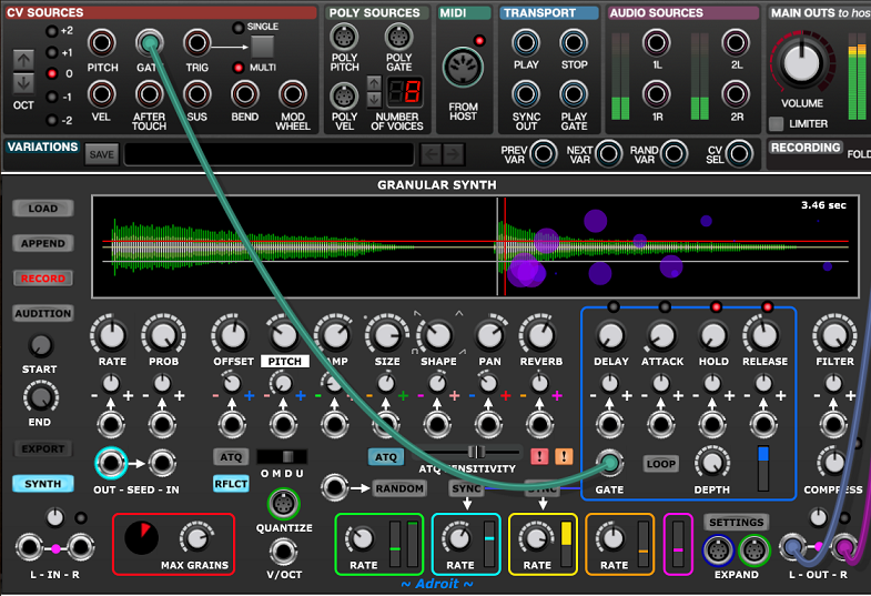
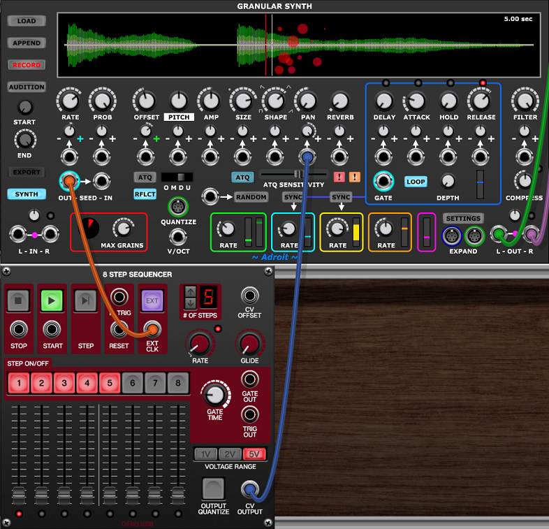
Sidechaining
When the Granular Synth is in Synth mode and nothing is connected to the audio inputs then the internal Envelope Follower tracks the module’s outputs. But if anything is patched to the IN sockets then the inputs signal(s) are tracked instead.
This means that any of the module’s parameters can be modulated by the strength of external signals. This is called sidechaining. The following patch shows an example…
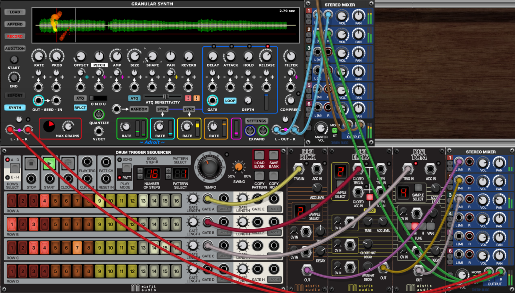
The modules in the lower cabinet form a simple drum machine and the stereo audio outputs are fed to the Granular Synth’s L-IN and R-IN sockets where they are mixed together and tracked by the Envelope follower. Here’s a snapshot of the signals…
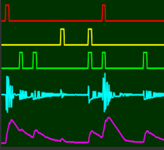
The top three traces show the drum module triggers, the cyan trace shows the audio signal (summed to mono) and the magenta trace shows the modulation signal from the Envelope Follower.
Inside the Granular Synth module the Envelope Follower modulates grain pitch, grain amplitude and filter cut-off frequency.
Finally the outputs of the drum machine and Granular Synth are mixed together and sent to the main outputs.
When using sidechaining you’ll probably find the input gain trim knob useful for scaling the effect that the input has on the Envelope Follower. It’s the small knob above the input sockets.