
This module is an optional add-on for the Granular Synth.
Please note that the Breakout module is sold separately and is NOT included in the Granular Synth bundle.
The breakout provides access to many different signals from within a Granular Synth, a mechanism for replacing the Granular Synth’s built-in reverb with external effects processing, a means to automatically trigger recording and a number of buttons that allow you to customize how the Granular Synth’s RANDOM button works. It also provides three handy utility sub-modules that enable you to do a certain amount of signal processing without having to load up additional modules.
You can use this module to apply modulation sources from a Granular Synth elsewhere in a patch or perhaps do some processing on one or more sources and then feed things back into the Granular Synth via its CV input sockets.
Table of Contents
Connection to the Granular Synth
Use a pair of cables to connect the FROM/TO GRANULAR SYNTH sockets of the breakout module to the EXPAND sockets of a Granular Synth.
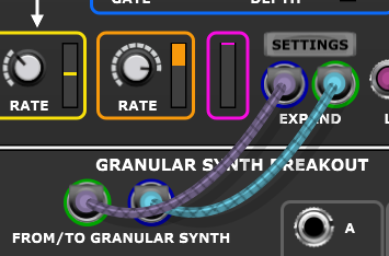
Voltage Modular only allows you to connect an input to an output (and vice versa) so it’s impossible to get the connection wrong.
Outputs
Many of the outputs are directly related to the internal modulation sources of the connected Granular Synth. Some signals are converted to unipolar range where this makes them easier to use in typical patches. The voltage range of each output is given in the descriptions below.
The colored dots next to some sockets are simply visual aids to help make it easier to understand how things are mapped. They match the color-coding used in the Granular Synth’s modulation system.
DENSITY
Range 0 V to 5 V.
This output corresponds to the Density internal modulation source. It is 5 volts multiplied by the number of grains divided by the maximum number of grains setting. So is 0 V when no grains are active rising up to 5 V as the number of grains approaches MAX GRAINS.
LFO1 SINE
Range -5 V to 5 V.
This corresponds to the LFO1 Sine internal modulation source.
LF01 COSINE
Range -5 V to 5 V.
This corresponds to the LFO1 Cosine internal modulation source.
LFO2
Range -5 V to 5 V.
This corresponds to the LFO2 internal modulation source. A triangular wave LFO that optionally resets to -5V when an envelope attack phase begins.
LFO3
Range -5 V to 5 V.
This corresponds to the LFO3 internal modulation source. A triangular wave LFO that optionally resets to 0V when an envelope attack phase begins.
LFO4
Range -5 V to 5 V.
This corresponds to the LFO4 internal modulation source. A Brownian LFO that provides a signal that’s an interesting mix of both periodic and random motion.
ENVELOPE FOLLOWER
Range 0 V to 5 V.
This corresponds to the Envelope Follower internal modulation source. It tracks the amplitude of the Granular Synth’s input signals or its output signals depending on whether anything is connected to the Granular Synth’s input sockets.
ENVELOPE
Range 0 V to 5 V.
This corresponds to the Envelope Generator internal modulation source. The Envelope Generator is a DAHR design with voltage control of each state.
GRAIN PITCH
Range 0 V to 1 V.
This corresponds to the Grain Pitch internal modulation source. This is calibrated at 1 V/Octave and gives the pitch offset ignoring the octave (in other words it’s the sub-octave interval and never actually reaches 1 V as it wraps around to 0 V when the next octave is reached).
GRAIN NOTE
Range 0 V to 14 V.
This socket outputs a voltage that represents the state of the arpeggiator inside the connected granular synth. It counts up when the Synth is in U mode and down in D mode. The maximum voltage output is the number of notes in the chord or scale minus one.
So for example in U mode with a four note chord the voltage will cycle like this… 0, 1, 2, 3, 0, 1, 2, 3 etc.
In D mode with a five note chord it will produce 4, 3, 2, 1, 0, 4, 3, 2, 1, 0 etc.
The maximum possible voltage is 14 V because the maximum number of notes that an S-Poly chord/scale signal can carry is 15.
MOUSE GATE
0 V or 5 V.
This output is 5 V when the left mouse button is down and the mouse cursor is over the Waveform Display of the connected Granular Synth and 0 V otherwise.
RECORD STARTED
0 V or 5 V.
This trigger output is briefly 5 V when recording starts as a result of the RECORD button being pressed on the connected Granular Synth (or a START RECORDING trigger being received).
If there’s no input connected to the Granular Synth then it loads up a demo sample instead of beginning recording. In this instance RECORD STARTED does not produce a trigger.
This output is useful for streamlining the capture of samples as it allows you to automatically trigger a sound when recording starts.
ENVELOPE RELEASE
0 V or 5 V.
This gate output is 5 V during the Release phase of the Envelope Generator.
ENVELOPE END
0 V or 5 V.
This trigger output is briefly 5 V when the Envelope Generator cycle ends.
FX SEND LEFT
Range -5 V to 5 V nominally.
This output is the signal that’s fed into the left channel of the Granular Synth’s built-in reverb.
FX SEND RIGHT
Range -5 V to 5 V nominally.
This output is the signal that’s fed into the right channel of the Granular Synth’s built-in reverb.
Inputs
START RECORDING
A standard trigger signal applied to this input socket tells the attached Granular Synth to start recording.
FX RETURN LEFT
Range -5 V to 5 V nominally.
If anything is connected to this input then the Granular Synth’s built-in reverb is bypassed and the signal fed to this socket is sent back to the Granular Synth and replaces the left channel output of the reverb. See the section below for more detail.
FX RETURN RIGHT
Range -5 V to 5 V nominally.
If anything is connected to this input then the Granular Synth’s built-in reverb is bypassed and the signal fed to this socket is sent back to the Granular Synth and replaces the right channel output of the reverb. See the section below for more detail.
Using external effects instead of the built-in reverb
The Granular Synth features a built-in reverb that’s useful and not too demanding on CPU but it’s not particularly high quality or flexible. So the Breakout module enables you to replace it with external effects processing. This might be higher quality reverb but could also be distortion, phasing, delay or anything you like.
The two FX SEND sockets output the stereo signals normally fed to the internal reverb while the two FX RETURN sockets allow you to bypass the built-in reverb unit entirely and feed the results of your “outboard” FX back into the Granular Synth’s signal path. Then they are mixed with the dry signals inside Granular Synth and pass through the stereo filter and compressor.
The difference between this arrangement and simply strapping external FX on to the outputs of the Granular Synth is not just that the signals go through the filter and compressor inside Granular Synth though. Exactly as when internal reverb is used, each and every grain has its own individual FX send parameter. So it’s easy to apply different amounts of external FX to different grains. And using modulation this can be done with precision. For instance you might want to only apply a delay effect to every fourth grain or only apply a chorus effect to the root note in a granular chord.
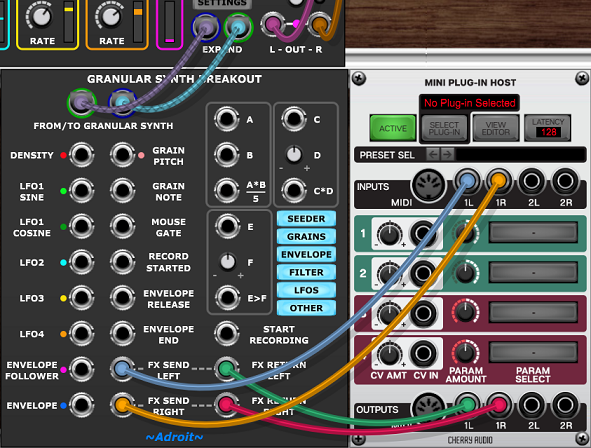
The image above shows how to wire up the send and return cables. In this instance to a Plug-In Host (allowing you to use practically any VST or AU plugin to process grains). But obviously you can use any modules that process signals inside Voltage Modular too.
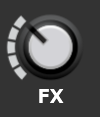
If either of the FX RETURN sockets are connected then the Granular Synth’s built-in reverb is disabled. This is indicated by the REVERB label on the Granular Synth changing to an FX label.

Control of randomization
When a Breakout module is not connected to a Granular Synth module then the Granular Synth’s RANDOM button randomizes grain parameters. However when a Breakout module is connected you can customize the randomization using the bank of buttons shown below.
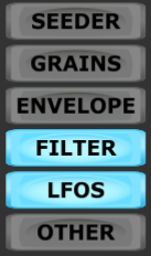
SEEDER
RATE and PROB parameters are randomized when this is engaged.
GRAINS
OFFSET, PITCH, AMP, SIZE, SHAPE, PAN and REVERB parameters are randomized when this is engaged.
ENVELOPE
DELAY, ATTACK, HOLD, RELEASE parameters along with LOOP and DEPTH are randomized when this is engaged.
FILTER
FILTER parameters are randomized when this is engaged.
LFOS
RATE settings for LFO1, LFO2, LFO3 and LFO4 are randomized when this is engaged.
OTHER
Offset ATQ, RFLT, OMDU Quantization, Size ATQ, LFO2 SYNC and LFO3 SYNC are randomized when this is engaged.
Utilities
The Breakout module provides three simple utility sub-modules. They enable you to perform a range of common signal processing tasks without the need to load up extra modules.
They operate completely independently so you are free to use them for tasks unrelated to any Granular Synth module.
Multiplier utility

This utility is a simple four-quadrant multiplier than can be used as a VCA or a ring modulator. The division by 5 is done in order to keep 5 V signals in range when multiplied.
Attenuvertor utility
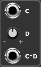
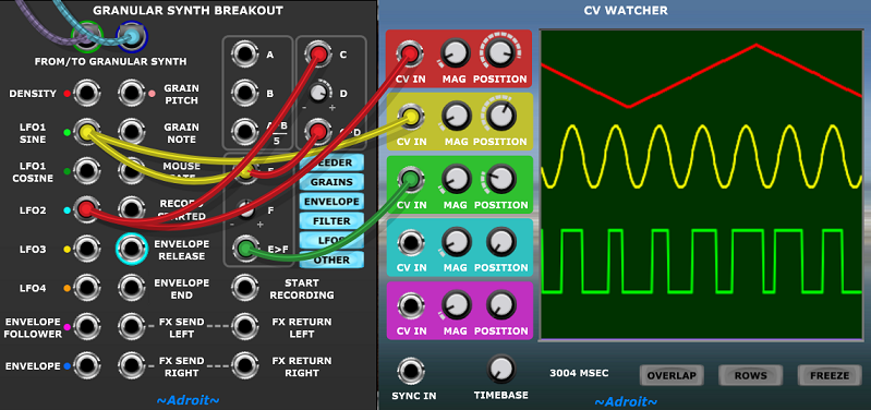
This is just a spare attenuvertor. So the knob D can be set to anything between -1 and +1 and the C*D output is the voltage fed to the C socket multiplied by the knob’s value.
Comparator utility
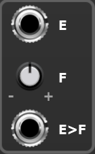
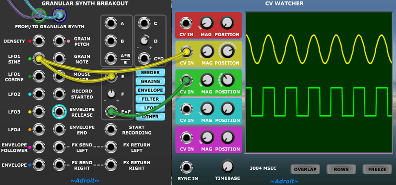
The knob F can be set to anything between -5 V and +5 V. The E>F output is 5 V if the voltage fed to the E socket is greater than the knob’s value, otherwise it’s 0 V.
Some example utility applications
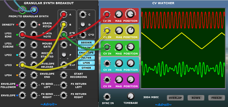
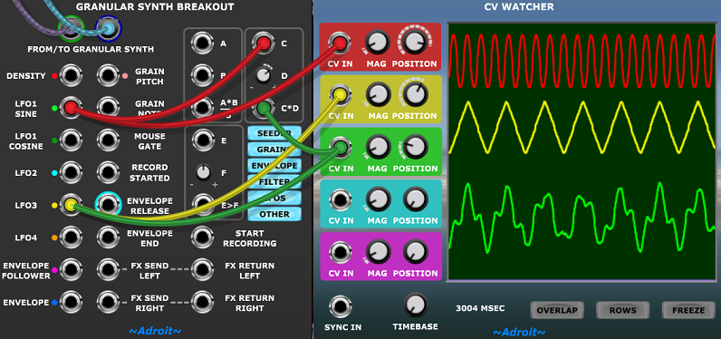
Here are a few examples of how you might use the built-in utilities to do some simple signal processing.
The CV Watcher is used just to show what’s going on but normally wouldn’t be present and the signal shown by its green trace would be fed to some modulation destination.
Availability
The Granular Synth Breakout module is available for download here.