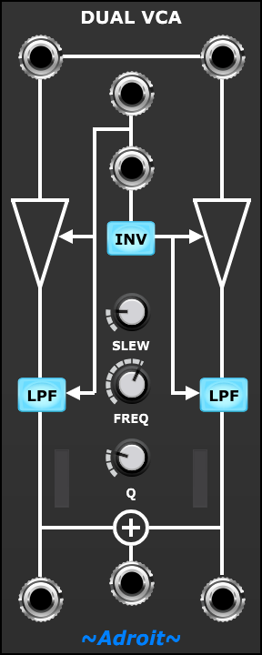
This module provides two voltage controlled amplifiers, two bypass-able voltage controlled filters, a CV inverter, a simple mixer and a pair of meters all configured with normalled connections to provide maximum functionality and convenience in a fairly compact space.
When either LPF button is engaged then a voltage controlled low pass filter is inserted in the signal path. The cutoff frequency of the filter is modulated by the signal controlling the VCA gain. This effectively turns the VCAs into West Coast style Low Pass Gates where loud signals are bright and quieter signals are duller. When fed with an envelope with a fast attack this produces something similar to a string pluck. When a slow attack is used the result is more like a brass sound.
The FREQ and Q knobs allow you to adjust the filter characteristics to taste.
Depending on how you connect the Dual VCA module and the setting of the LPF (low pass filter) and INV (invert) toggle buttons it can serve as any of the following…
- Two independent VCAs / LPGs
- A stereo VCA / LPG
- A voltage controlled cross-fader
- A voltage controlled panner
- A voltage controlled two-channel mixer
The four sockets at the top are inputs, the three at the bottom are outputs.
Hopefully, it is fairly obvious from the schematic legend how things work.
If only one of the input sockets at the very top is connected then the horizontal line between them indicates that the other VCA will receive a copy of the signal.
The two sockets in the middle of the upper half of the module are the CV inputs. The top one will control the gain/cutoff of both VCAs/VCFs if the lower CV input socket is not connected to anything.
If the INV button is engaged then the CV for the right-hand VCA/VCF is inverted. In other words a CV of 5 volts will result in zero gain / minimum cutoff and a CV of 0 volts will result in maximum gain / maximum cutoff.
The SLEW knob enables sudden changes in the control voltage affecting the VCA gain and VCF cutoff to be slowed down slightly. This feature can be used to eliminate nasty popping and clicking noises caused by abruptly switching an audio source on or off (or just sudden changes in amplitude) but can also be used as a creative tool to provide subtle control over transients.
These effects can vary from being so subtle as to be unnoticeable to being really obvious depending on the exact nature of the CV and audio signals involved.
At the SLEW knob’s minimum setting no slew is applied. At maximum setting a very soft 20 milliseconds/volt slew is applied. 12 o’clock produces a useful 5 ms/V . The default setting is 1 ms/V which gives attacks a reasonable snap while still supressing most artifacts.
In the CV Watcher image below the red trace shows a rapidly changing CV input, the yellow trace shows its impact on an audio signal when slew is set at minimum, while the green trace show the impact with maximum slew.
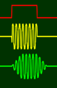
Notice the sudden jump from zero at the beginning of the yellow trace pulse. It’s such discontinuities that cause the clicking and popping artifacts to occur. Even when the jump to/from zero is minimal or non-existent there is still noise caused by abrupt change.
The FREQ and Q knobs only works when one or more of the LPF buttons are engaged.
The FREQ knob offsets the modulation from the VCA gain control voltages allowing you to adjust the range of cutoff frequencies for a variety of filter sweep effects.
The Q knob controls the resonance of the VCFs. At minimum setting the filters act like low pass shelfs but at higher Q settings emphasis is added around the cutoff frequency. This narrow emphasis can make some inputs sound a lot quieter so a makeup gain is applied to counter this, however at maximum Q this might result in some signals becoming excessively amplified so watch out for this if distortion is a concern.
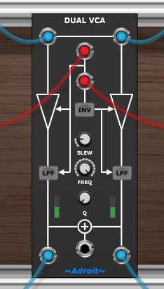
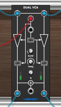
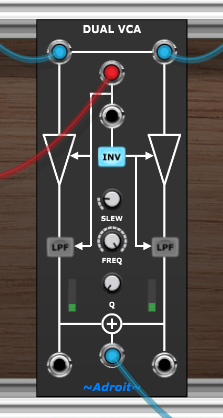
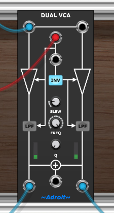
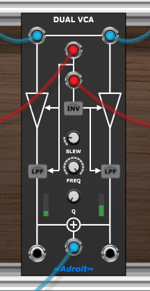
Another useful configuration is to use the VCAs/LPGs in series with one controlled by an envelope generator and the other controlled by a velocity signal.
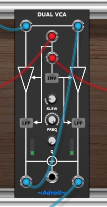
Then the LPF buttons can be used to independently determine whether filtering is applied inside the envelope of each note, in proportion to velocity, both or neither.
Another application for connecting the VCAs in series is to change the amplitude response curve, effectively squaring the law, typically to produce a more aggressive decay as shown in the image below…
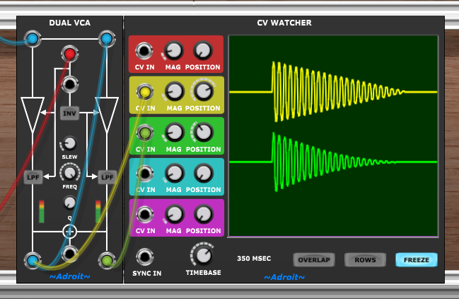
Patching in series with the LPF buttons engaged will also produce a more aggressive filter cutoff response.
Availability
The Dual VCA module is part of LSSP XL and the Adroit Toolkit. It is also available as an individual module.