Table of Contents
Introduction
The Custom IO module is part of the Adroit Custom bundle.

Although Custom Panel modules don’t contain any sockets, up to four Custom IO modules can be used to enable wired communication between Custom Panel modules and other modules.
Each Custom IO module has a MIDI input, a MIDI output, 8 CV/audio inputs, 8 CV outputs and 8 VCA pairs.
User-editable labels are provided to help with identification.
Each Custom IO module has a Bank setting of either A, B, C or D. The bank setting is displayed in a large font so it’s easier to see where say input A3 or output C6 is when using multiple Custom IO modules.

When you have multiple Custom IO modules in a patch make sure they are set to different Banks.
One possible source of confusion is that CV output values and VCA gains persist (even beyond Voltage Modular sessions). This is a side effect of the way the invisible communication between Custom Panel and Custom IO modules works. It doesn’t have any practical impact on correctly configured patches but may give you unexpected results when you are in the middle of wiring something up. You may for instance be expecting a CV output socket to deliver 0 V when it’s not mapped to anything but it could be some other voltage depending on previous usage.
Mapping
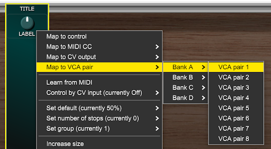
When you right-click on a control on a Custom Panel module you get a menu that includes various mapping options…
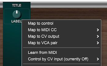
Each control can have up to four independent mappings at once. See the Custom Panel documentation for more details.
The Map to control option makes a control remotely control a knob, slider or button on another Voltage Modular module while the other options all relate to Custom IO modules.
Map to MIDI CC
The Map to MIDI CC options makes a control transmit MIDI CC messages from a Custom IO MIDI OUT socket when the control is changed.

The LED next to the MIDI OUT socket flashes whenever a MIDI message is transmitted.

Map to MIDI Command
Push buttons behave slightly differently in that they have a Map to MIDI command option rather than Map to MIDI CC.

Start transmits a MIDI start message when the button is pressed. Stop transmits MIDI stop and Continue transmits MIDI continue. These options enable you to add buttons to your custom interface that control the transport of MIDI sequencers.
Program Change transmits a MIDI program change message when the button is pressed. This enables you to add buttons to your interface that change the patch on any connected MIDI kit. A series of menus pop-up so that you can select the Custom IO Bank, MIDI Channel, MSB, LSB and Program number.
All notes off transmits a MIDI all notes off message and is useful if any MIDI notes get accidentally stuck on during rewiring.
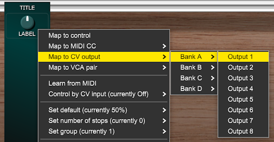
Map to CV Output
The Map to CV output option makes a control send a control voltage to a particular Custom IO CV OUT socket.
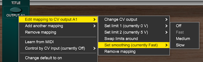
A very useful feature when mapping a control to a CV output is that you can specify the voltage range by setting limit 1 and limit 2 in the Custom Panel module’s right-click menu system. With a knob, limit 1 refers to its fully CCW setting while limit 2 refers to its fully CW setting.
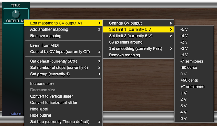
By default limit 1 is set to 0 V and limit 2 is set to 5 V but there are lots of other options available. The cents and semitones options produce the desired voltages when standard 1 V per octave voltage control of pitch is used.
Another useful feature is being able to set the number of stops. When the number of stops is 0 a knob or slider is continuously variable but when stops are set there are a limited number of control positions. In effect this turns knobs into rotary switches and sliders into slide switches.
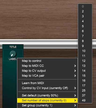
When combined with voltage limits this means you can create controls that have precise discrete settings. For instance if you have a knob with limit 1 set to -7 semitones, limit 2 set to +7 semitones and number of stops set to 15 then the result is a rotary switch that outputs pitch control voltages that have precise semitone steps.
Map to VCA Pair
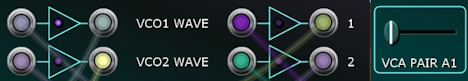
The Map to VCA pair option makes a control determine the gain settings for a pair of VCAs.
VCA Pairs
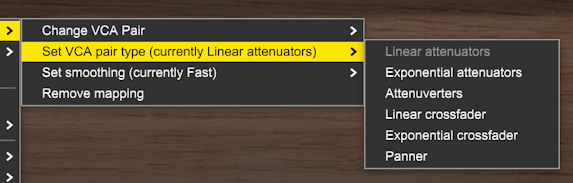
The VCA pairs can be configured to work as stereo attenuators, attenuverters, crossfaders or panners.
Often you’ll only need a single VCA but having pairs means you have the option of dual or stereo use plus several other interesting possibilities.
If only the left-hand VCA’s input is connected then the right-hand VCA gets a normalled copy of the same signal. The IN(M) label is a reminder of this – with M standing for mono. So if you are using a VCA pair as a panner then the input signal only needs to the fed to the IN(M) socket. The panned outputs are available, as you’d expect, from the two outputs of the VCAs. However, there’s no normalization of outputs so when using a VCA pair as a crossfader you need to sum the outputs of the VCAs together yourself.
The following descriptions talk about the control being a knob but the same applies if the control is a slider or joystick.
Linear attenuators configures the knob to control the gain of both VCAs in a linear fashion. The gain is 0 when the knob is fully CCW and 1 when fully CW. Gain at 12 o’clock is 0.5.

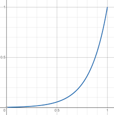
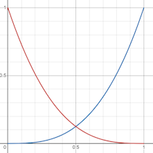
Exponential attenuators similar to the linear attenuator mode but the control uses the exponential curve shown below and is therefore more suitable for things like volume control. Gain when a knob is at 12 o’clock is approximately 0.05625.
Attenuverters provides dual linear attenuvertors. Gain is -1 when the knob is fully CCW and 1 when the knob is fully CW. Gain at 12 o’clock is 0.

Linear crossfader the left VCA operates as a linear attenuator while the right VCA’s gain is the inverse (1 – gain).
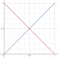
Exponential crossfader as linear crossfading but with cubic curves.
Panner this uses sine pan law.

Button Control of VCA Pairs
If a VCA pair is controlled by a button instead of a knob, slider or joystick then obviously there are only two control states and the VCAs are either open or closed depending on the state of the button. In other words VCA pairs operate as switches when controlled by buttons.
In attenuator mode both VCAs have the same gain of 0 or 1, in attenuverter mode both VCAs have the same gain of -1 or 1, in the other modes when the gain of one VCA is 0 the gain of the other is 1.
This enables you to use the VCA pairs to switch signals on and off or redirect them.
When switching audio signals if the VCAs open or close instantly this introduces popping and clicking artifacts so there is a Smoothing option that slows down the change in gain.
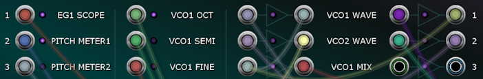
The Slow option creates a gentle fade in or out. You can see the effect of slow smoothing by examining the signals with Custom Panel scopes…

MIDI Learn
Returning to the menu that pops up when a control on a Custom Panel module is right-clicked…

We see that beneath the mapping options we have two more options related to Custom IO.
Learn from MIDI listens for a MIDI CC or a note on message from Bank A’s MIDI IN socket and assigns that to the control so that subsequent messages that use the same CC or note control the control. So for instance if you want the Mod Wheel on a keyboard to control a particular knob in your interface then select Learn from MIDI in the knob’s menu and move the Mod Wheel slightly. The Mod Wheel will then control the knob. As another example you might want to be able to switch a toggle button on and off using a particular key on a keyboard or a particular button on MIDI control surface. It’s the same process – select Learn from MIDI then press the key or button.
The MIDI IN socket is normalled to the MIDI FROM HOST output on Voltage Modular’s I/O Panel so you usually don’t need to use a cable if the MIDI is coming from there. However, if the MIDI is coming from somewhere within your patch then obviously a cable is required.
Only the MIDI IN of the Custom IO module designated as Bank A accepts MIDI input. This should be sufficient as Voltage Modular performs MIDI merging when multiple MIDI cables are patched into the same input. So if you need to mix two MIDI streams together simply plug both cables into the MIDI IN socket on Bank A.
MIDI Learn only works when there is a Custom IO module in the patch that is set to Bank A.
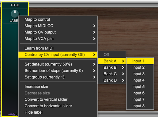
Control by CV Input
The Control by CV input option allows the setting of a knob, slider or button on a Custom Panel to be controlled by CV from a Custom IO CV IN socket.
Adroit Custom maps 0 V to a control’s minimum position and 5 V to its maximum. Voltages outside this range are clamped. For buttons 2.5 V and above is considered on.
When a control is being controlled by CV input you will no longer be able to set it manually as any manual setting will constantly be being overriden by the CV. Although this might change in a future update as it would be useful if you could do manual override when the voltage was constant.
Creative Applications
By using a Custom Panel control as a communications intermediary you can do some interesting things that might not be immediately obvious.
For instance by combining Learn from MIDI with Map to CV output any knob, slider, wheel, button or key in your MIDI rig can become a control voltage source.
By combining Control by CV input with Map to MIDI CC you can convert CV to MIDI CC.
By combining Control by CV input with Map to MIDI command you can make trigger signals in Voltage Modular start and stop external MIDI sequencers or change patches on external MIDI kit.
By combining Control by CV input with multiple types of mapping you could make a slow LFO twiddle a knob on some Voltage Modular module, adjust a parameter in your MIDI rig via CC while doing a spot of crossfading with a VCA pair. As you can set up four different mappings and use different limits you can get some fairly complex “macro” action going on.
One idea might be to map the bottom octave for your MIDI keyboard to various functions other than playing notes. You could use the Voltage Modular Splitter module to remove the bottom octave from MIDI signals sent to your main voice then teach a number of Custom Panel push buttons to respond to particular keys in the unfiltered MIDI signal.
In turn these push buttons could be mapped to Custom IO CV outputs so that pressing a particular key in the bottom octave produces a trigger for something such as a drum module. Or the push buttons could be mapped to transmit program change messages that change patches.
Perhaps you could link a button on a MIDI control surface to a Custom Panel toggle button and then map the button to several VCA pairs working as two-way switches so that hitting the button flips your Voltage Modular patch’s wiring between two very different configurations.
Helpful Extra Features
As you can no doubt see this is a pretty flexible setup.
As well as driving any number of knobs, sliders and buttons your custom interface can output up to 32 different CV signals and use the VCA pairs as up to 32 switches, attenuators, attenuverters, crossfaders or panners. This enables your interface to rewire patches, control modulation and perform various mixing duties without the need for other utility modules beyond Custom IO. In addition, as there can be four separate MIDI outputs, you can have up to 64 channels of MIDI CC control which means you can address up to 8,192 different CC targets. You can also stop and start sequencers and change patches on external MIDI kit. On top of that your interface can itself be controlled by MIDI or via 32 different CV inputs.
With so much potentially going on in relation to a Custom IO module there are a few features designed to hopefully make things a little less confusing…
There are 24 user-editable text fields. Double-click on any of the “LABEL” text fields to enter short but meaningful descriptions of what particular inputs, outputs or VCA pairs are being used for.
You may be tempted to not bother labelling, especially when you begin a project and there are only one or two inputs and outputs in use, but it’s a good idea to get in to the habit of always labelling things.
Note that the user-editable labels can only be changed if the Custom Look EDIT LABELS button is engaged.
There are some useful line graphics. These are rather subtle with the default Dark Theme settings (as the outlines don’t contrast much with the background) but if you turn up the outline brightness on Custom Look they become more obvious.
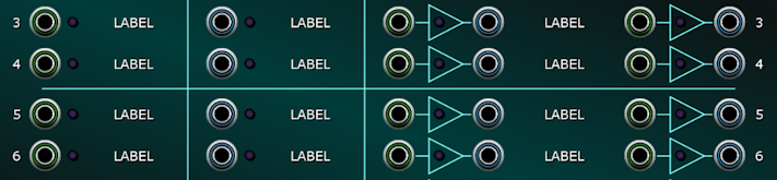
The triangular symbols represent individual VCAs. The input, output and VCA pair sections are separated by vertical lines. There’s also a single horizontal line between rows 4 and 5. This isn’t because there is any functional difference between rows 1-4 and 5-8 it’s just there as a visual aid.
There are 34 LEDs. Each CV/audio input, CV output and VCA has an associated LED. For the inputs and outputs these function as crude rectifying voltmeters. So 0 V results in the LED being off, +5 V or above results in full brightness, -5 V or below also results in full brightness and anything between gives proportionate brightness depending on how far away from 0 V the signal is. When audio is fed to an input the LEDs aren’t very effective as they only sample the input about 10 times per second but you should still see the odd flicker to indicate there is a signal providing that the amplitude is fairly high.
Note that the input LEDs work regardless of whether any Custom Panel elements are examining their signal. So you can use spare ones as general-purpose signal testers.
The LED inside a VCA symbol indicates the gain of that VCA. So for instance if a horizontal slider is mapped to control a VCA pair that’s configured as a crossfader then when the slider is to the left the LED for the left-hand VCA will be fully lit and the right-hand one will be dark and so on.
As with the input and output voltmeter LEDs the gain is rectified so when a VCA is configured as an attenuverter increasing negative gain results in increased LED brightness. So if a knob is mapped to control a VCA pair that’s configured as a dual attenuverter the LEDs will be dark when the knob is at 12 o’clock.
The MIDI IN and MIDI OUT sockets also have an LED that flashes when they receive or transmit messages.

Even though the LEDs only operate at a low sample rate they still place an undesirable load on the CPU so there’s a toggle button to switch them on and off. Leave the LEDs switched off when you aren’t troubleshooting.

The MIDI input and output indicator LEDs aren’t affected by the setting of the LEDS button so always work.
You’ll often end up with situations where you want to sum or distribute multiple signals and want to keep the wiring tidy so to help a little there are two very simple multiples at the bottom-right of the module.

The line graphics between the sockets shows how they are wired internally.